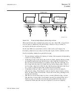
isolated, or if the disconnectors operate in parallel to other closed connections, or
if they are grounding on both sides.
•
Circuit breaker closing is only interlocked against running disconnectors in its bay
or additionally in a transformer bay against the disconnectors and grounding
switch on the other side of the transformer, if there is no disconnector between CB
and transformer.
•
Circuit breaker opening is only interlocked in a bus-coupler bay, if a bus bar
transfer is in progress.
To make the implementation of the interlocking function easier, a number of
standardized and tested software interlocking modules containing logic for the
interlocking conditions are available:
•
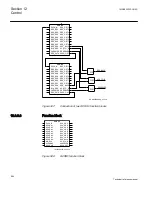
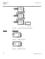
Line for double and transfer busbars, ABC_LINE (3)
•
Bus for double and transfer busbars, ABC_BC (3)
•
Transformer bay for double busbars, AB_TRAFO (3)
•
Bus-section breaker for double busbars, A1A2_BS (3)
•
Bus-section disconnector for double busbars, A1A2_DC (3)
•
Busbar grounding switch, BB_ES (3)
•
Double CB Bay, DB_BUS_A(3), DB_LINE(3), DB_BUS_B(3)
•
Breaker-and-a-half diameter, BH_LINE_A, BH_CONN, BH_LINE_B (3)
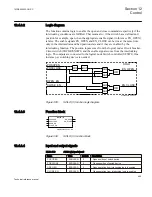
The interlocking conditions can be altered, to meet the customer specific requirements,
by adding configurable logic by means of the graphical configuration tool PCM600.
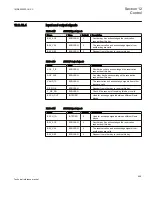
The inputs Qx_EXy on the interlocking modules are used to add these specific conditions.
The input signals EXDU_xx shall be set to true if there is no transmission error at the
transfer of information from other bays. Required signals with designations ending in
TR are intended for transfer to other bays.
12.4.3
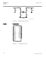
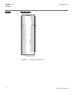
Logical node for interlocking SCILO (3)
12.4.3.1
Introduction
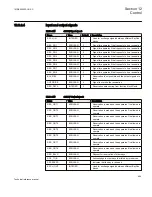
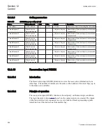
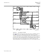
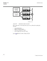
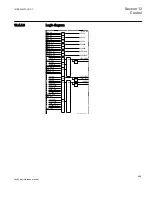
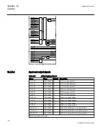
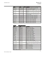
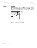
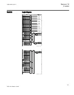
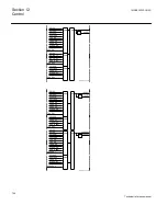
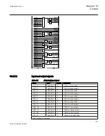
The Logical node for interlocking SCILO(3) function is used to enable a switching
operation if the interlocking conditions permit. SCILO (3) function itself does not
provide any interlocking functionality. The interlocking conditions are generated in
separate function blocks containing the interlocking logic.
Section 12
1MRK505222-UUS C
Control
694
Technical reference manual
Summary of Contents for Relion 670 series
Page 1: ...Relion 670 series Line differential protection RED670 ANSI Technical reference manual...
Page 2: ......
Page 40: ...34...
Page 50: ...44...
Page 60: ...54...
Page 126: ...120...
Page 384: ...378...
Page 496: ...490...
Page 556: ...550...
Page 602: ...596...
Page 620: ...614...
Page 794: ...788...
Page 864: ...858...
Page 988: ...982...
Page 998: ...992...
Page 1084: ...1078...
Page 1164: ...1158...
Page 1168: ...1162...
Page 1220: ...1214...
Page 1230: ...1224...
Page 1231: ...1225...

