5
5.9
Parameter overview of PROFIBUS–DP
5-311
Siemens AG 2005 All Rights Reserved
SIMODRIVE 611 universal Description of Functions (FBU) – 04.05 Edition
Table 5-38
Parameters for PROFIBUS–DP, continued
Parameters
No.
Effec-
tive
Units
Max.
Stan-
dard
Min.
Description
1783:64
Received parameterizing data
PROFIBUS (from SW 3.1)
–
–
–
hex
RO
1784:64
Received configuration data
PROFIBUS (from SW 3.1)
–
–
–
hex
RO
P1783:64
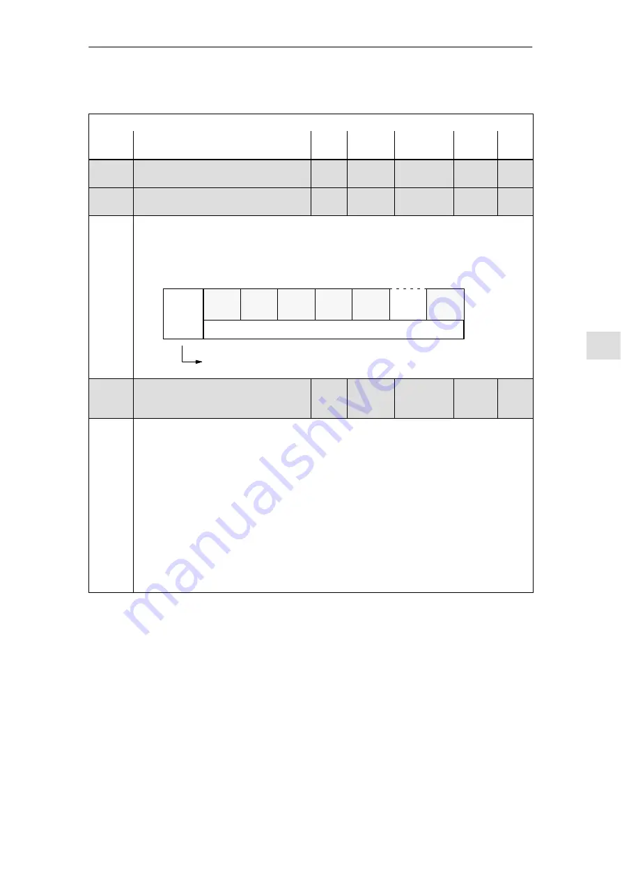
... is an image of the parameterizing data received from the DP slave
(refer to Chapter 5.8.5).
P1784:64
... is an image of the configuration data received from the DP slave
(refer to Chapter 5.7.1).
Index
:0
:1
:2
:3
:4
:5
etc.
No. of
valid
bytes
Image of the parameter or configuration data
= 0 ––> Neither parameterizing nor configuration data available
1st byte 2nd byte 3rd byte 4th byte 5th byte
nth byte
1785:13
(from
SW 3.1)
Extended PROFIBUS diagnostics
–
–
–
hex
RO
... contains diagnostics information to operate PROFIBUS. The following applies for the indi-
vidual indices of P1785:
:0 Error master sign–of–life since POWER ON
:1 Clock–cycle synchronous operation selected
:2 Interpolation clock cycle (Tipo) in us
:3 Position controller clock cycle (Tlr) in us
:4 Master application cycle type (Tmapc) in us
:5 DP cycle time (Tdp) in us
:6 Data exchange time (Tdx) in us
:7 Instant in time of the setpoint sensing (To) in us
:8 Instant in time of the actual value sensing (Ti) in us
:9 PLL window (Tpllw) in 1/12us
:10 PLL delay time (Tplld) in 1/12us
:11 External slave–to–slave communication connections
:12 Internal slave–to–slave communication connections
5 Communications via PROFIBUS DP
08.99
10.99
08.01


