TBCTL[SYNCOSEL]
TBPRD
Period Active
TBPRD
Period Shadow
16
TBCTL[SWFSYNC]
CTR = PRD
TBPHS
Phase Active Reg
Counter
UP/DOWN
16
Sync
Out
Select
EPWMxSYNCO
Reset
Load
16
TBCTL[PHSEN]
CTR = Zero
CTR = CMPB
Disable
X
EPWMxSYNCI
TBCTL[PRDLD]
TBCTR[15:0]
Mode
TBCTL[CTRMODE]
CTR = Zero
CTR_max
TBCLK
Clock
Prescale
SYSCLKOUT
TBCLK
TBCTL[HSPCLKDIV]
TBCTL[CLKDIV]
CTR_dir
TBCTR
Counter Active Reg
clk
Max
Dir
Zero
DCBEVT1.sync
(A)
DCAEVT1.sync
(A)
A. These signals are generated by the digital compare (DC) submodule.
ePWM Submodules
682
SPRUHE8E – October 2012 – Revised November 2019
Copyright © 2012–2019, Texas Instruments Incorporated
C28 Enhanced Pulse Width Modulator (ePWM) Module
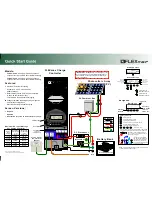
The block diagram in
shows the critical signals and registers of the time-base submodule.
provides descriptions of the key signals associated with the time-base submodule.
Figure 7-5. Time-Base Submodule Signals and Registers
A
These events are generated by the type 2 ePWM digital compare (DC) submodule based on the levels of the TRIPIN
inputs [For Example: COMPxOUT and TZ signals].
Table 7-5. Key Time-Base Signals
Signal
Description
EPWMxSYNCI
Time-base synchronization input.
Input pulse used to synchronize the time-base counter with the counter of ePWM module earlier in the
synchronization chain. An ePWM peripheral can be configured to use or ignore this signal. For the first ePWM
module (EPWM1) this signal comes from a device pin via GPTRIP6. For subsequent ePWM modules this
signal is passed from another ePWM peripheral. For example, EPWM2SYNCI is generated by the ePWM1
peripheral, EPWM3SYNCI is generated by ePWM2 and so forth. See
for information on the
synchronization order of a particular device.
EPWMxSYNCO
Time-base synchronization output.
This output pulse is used to synchronize the counter of an ePWM module later in the synchronization chain.
The ePWM module generates this signal from one of three event sources:
1.
EPWMxSYNCI (Synchronization input pulse)
2.
CTR = Zero: The time-base counter equal to zero (TBCTR = 0x00).
3.
CTR = CMPB: The time-base counter equal to the counter-compare B (TBCTR = CMPB) register.
CTR = PRD
Time-base counter equal to the specified period.
This signal is generated whenever the counter value is equal to the active period register value. That is when
TBCTR = TBPRD.
CTR = Zero
Time-base counter equal to zero
This signal is generated whenever the counter value is zero. That is when TBCTR equals 0x00.