EZZ023536
6/16
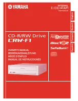
• Connection Using MEMOBUS/Modbus Communications
The host device reads Load Share SFS Output Register 826H (U9-07) of the master and
writes it to Slave Register Address 0002H (Frequency Reference) to set the frequency
reference of the slave. The host device reads the value of Load Share Torque Output
Register 827H (U9-08) of the master and writes it to Slave Register Address 0004H
(Torque Reference) to set the torque reference of the slave. The following tables give the
register addresses of the master and slave and the communications operations.
Operation Register Addresses for Load Share Master
Register No.
Description
0001H
Run command
bit 0
When H5-12 = 0: Forward Run/Stop, 1: Forward Run, 0: Stop
When H5-12 = 1: Run/Stop, 1: Run, 0: Stop
bit 1
When H5-12 = 0: Reverse Run/Stop, 1: Reverse Run, 0: Stop
When H5-12 = 1: Forward/Reverse, 1: Reverse, 0: Forward
0002H
Frequency
reference
The unit is set with o1-03 (Frequency Display Unit Selection).
Monitor Register Addresses for Load Share Master
Register No.
Description
826H (U9-07)
Load Share SFS
Output
The unit is set with o1-03 (Frequency Display Unit Selection).
827H (U9-08)
Load Share Torque Output (0.1%, signed)
Operation Register Addresses for Load Share Slave
Register No.
Description
0001H
Run command
bit 0
When H5-12 = 0: Forward Run/Stop, 1: Forward Run, 0: Stop
When H5-12 = 1: Run/Stop, 1: Run, 0: Stop
bit 1
When H5-12 = 0: Reverse Run/Stop, 1: Reverse Run, 0: Stop
When H5-12 = 1: Forward/Reverse, 1: Reverse, 0: Forward
0002H
Frequency
reference
The unit is set with o1-03 (Frequency Display Unit Selection).
0004H
Torque reference/torque limit (0.1%, signed)
Figure 3.4 MEMOBUS/Modbus Communications Operation Diagram
0001H (Run Command)
0002H (Frequency Reference)
Host device
←
Master
Host device
→
Master
Host device
←
Master
Host device
→
Slave
Write
0001H (Run Command)
0002H (Frequency Reference)
0004H (Torque Reference)
Operation at host
device & master start
Operation repeats while running
Host device
→
Master
Response
Read Response
Host device
←
Slave
Response
Time
24 bit
H5-06 Setting
24 bit
Drive transmit
wait time
24 bit
H5-06 Setting
24 bit
Drive transmit
wait time
24 bit
H5-06 Setting
Write
Содержание CR700
Страница 1: ......
Страница 2: ...This Page Intentionally Blank 2 YASKAWA SIEPC71061723A YASKAWA AC Drive CR700 Technical Manual ...
Страница 244: ...3 13 Test Run Checklist 244 YASKAWA SIEPC71061723A YASKAWA AC Drive CR700 Technical Manual ...
Страница 422: ...7 7 Storage Guidelines 422 YASKAWA SIEPC71061723A YASKAWA AC Drive CR700 Technical Manual ...
Страница 426: ...8 2 Disposal Instructions 426 YASKAWA SIEPC71061723A YASKAWA AC Drive CR700 Technical Manual ...
Страница 837: ...EZZ023535 2 35 1 Revision History Revision Revised Content Date First Edition 2017 08 ...
Страница 872: ...EZZ023536 2 16 Revision History Revision Revised Content Date First Edition 2017 08 ...