


6-8
TI71M01D06-01EN 3rd Edition: 2012.12.01
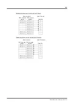
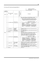
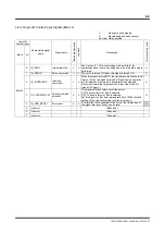
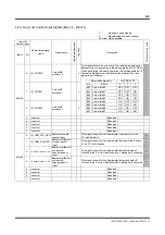
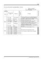
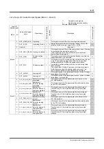
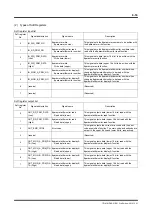
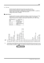
List of Logic I/O Contact Input Signals (Block 3)
: Frequently
used
signals
Δ
:
Signals assigned as necessary
No mark: Not applicable
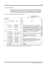
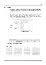
Logic I/O
Contact input
Abbreviated signal
name
Signal name
Table data op
era
tion
Jog move
Description
I/O pr
ocessing cycle
Block bit
Block 3
0 IN_EMG
Immediate
stop
Δ
Δ
See Section “6.1.5 Process Settings in Error State" for
explanation about error processing when the immediate stop is
performed.
H
1 IN_SERVO
Servo
command
The servo is turned ON when this signal is turned ON.
H
2 IN_INTERLOCK
Interlock
command
Δ
Δ
While this signal is turned ON, the velocity override value is set
to zero. (When this signal is turned ON, positioning operation
is interrupted and the motor is decelerated and stopped.
Movement toward the target position is resumed when it is
turned OFF again.)
H
3 IN_OVERRIDE_SEL
Velocity override
selection
Δ
Δ
This signal switches velocity override values.
ON: The scale factor of #45 is selected.
OFF: The scale factor of #44 is selected.
Set this signal to off and set parameter #44 to 10000 (default
setting ) if the velocity override function is not used.
H
4 IN_ERR_RESET Error
reset
Δ
Δ
All errors that have occurred at the time of the rising edge of
this signal are reset, if they can be reset.
L
5 (reserve)
(Reserved)
6 (reserve)
(Reserved)
7 (reserve)
(Reserved)