


5-13
TI 71M01D06-01EN 3rd Edition: 2012.12.01
1
2
10
9
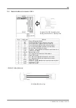
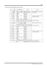
5.8 Analog Monitor Connector <CN3>
Pin No.
Signal name
Definition
1
VEL
Velocity monitor terminal
2
AM1
Analog monitor terminal 1 (general purpose monitor 1)
3
AM2
Analog monitor terminal 2 (general purpose monitor 2)
4
DM1
Digital monitor terminal 1 (general purpose monitor 1)
5
DM2
Digital monitor terminal 2 (general purpose monitor 2)
6 T-R
Current
command
7 T-T
Reserved
8 T-S
Reserved
9
<Prohibited>
Reserved Do not connect any line.
10
GND
GND terminal for monitor
These signals are used for observation and troubleshooting only! Do not use them as
feedback data to controllers. Make sure to use the analog monitor card (optional) to observe
these signals.
CAUTION
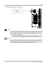
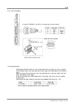
It is possible to monitor various states of the drive using the analog monitor
card (optional).
Analog monitor card (optional, R7041WC)
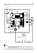
<CN3> connector