


8-20
TI71M01D06-01EN 3rd Edition: 2012.12.01
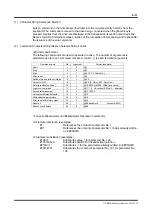
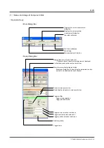
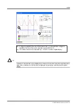
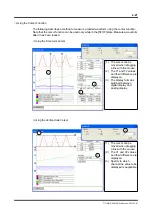
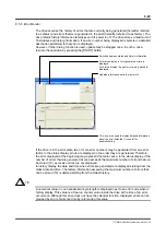
Understanding an Overview of Motor Operation in AUTO Trigger Mode
It is possible to understand a rough behavior of the motor by setting a long range time axis
and monitoring waveforms by AUTO trigger while the motor is operating.
If the time axis is set to display a long range (200 msec/div) as shown in the screen above,
due to sampling issues the display may show waveforms that differ from the actual operation
waveforms and timing. Always take aliasing problems into account before using the
equipment.
(1) Position command differential value (velocity profile) to be generated by the
controller
(2) Actual velocity information. Because there are four peaks within the range indicated
by a bracket, it shows that the motor moved triangularly four times.
(3) [Axis operation active], [Drive operation active] and [In position status] are assigned
from the top in digital waveform display.
(4) It can be observed that the rise of the axis operation signal and the rise of #359 have
the same timing.
(5) It can be observed that the positioning status signal rises at almost the same time as
the move completion.
CAUTION
3
7
1
2
4
5