


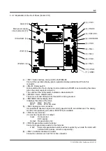


5-7
TI 71M01D06-01EN 3rd Edition: 2012.12.01
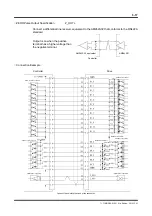
470Ω
2.7kΩ
COMP0
XORG
XOTD
XOTU
100kΩ
10kΩ
0.01μF
Vcc
PS2805
PS2702
ERR+
Vcc
ERR‑
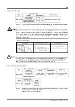
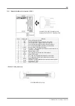
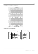
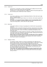
5.5 Sensor
Terminal
<TB4>
Pin No. Signal name
Definition
1 COMP0
Sensor
power
2
XORG
Home input B-contact
3
XOTD
- EOT input B-contact
4
XOTU
+ EOT input B-contact
5 ERR+
Regen. Resistor error
6 ERR-
Regen. Resistor error
output -
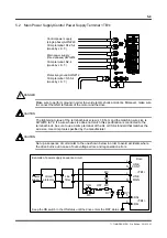
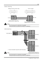
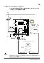
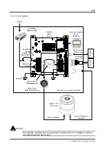
Make sure to set up a sequence circuit as shown in Section 3.2, "Main Power Supply/Control
Power Supply Terminal <TB1>" in order to avoid accidents where the drive fails due to
over-voltage errors and/or regeneration errors.
CAUTION
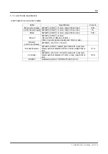
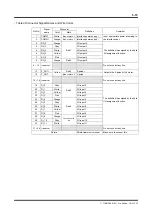
Sensor input specification
Rated voltage
12 to 24VDC (±10%)
Rated input current
4.1 mA/point (at 12VDC)
8.5 mA/point (at 24VDC)
Input impedance
3.0 k
Ω
Operating voltage (relative
to COMP0)
Off: Less than 3.0VDC
On: 9.0VDC or more
Allowable leak current
Guarantee OFF at 1.0
mA or less
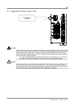
Regeneration error output
Maximum service voltage 30VDC
Maximum output current 50 mA
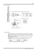
Connector: 733-106 (made by WAGO)
Insulation stripping length: 5mm
The connector can be attached through one-touch operation by pulling
down the spring in the slot in the upper part of the connector using a drive.
(The size of the tip of a drive is 2.0 x 0.4mm.)
Wire size: AWG#28 to AWG#20