


6-5
TI71M01D06-01EN 3rd Edition: 2012.12.01
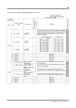
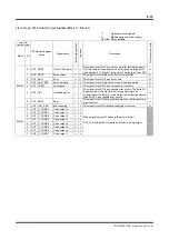
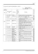
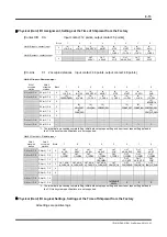
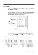
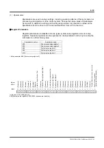
Logic I/O
Logic I/O signals are host signals of hard I/O and comprised of 8 input blocks and 8 output
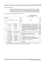
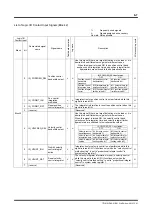
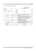
blocks. Each block consists of 8 bits (8 different signal types). See Section 6.1.1 (3), "Types of
Logic I/O" for the signal names and definition of each bit.
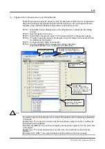
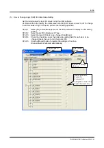
Logic I/O Initial Value Setting
It is possible to fix the input status of signals that are not assigned to hard I/O inputs by setting
their status to the initial value. This way, it is possible to reduce the number of points in the
limited number of hard I/O points. See Section 6.1.1 (5), "How to Change Logic (Soft) I/O
Initial Value Setting" for how to make this setting.
<Usage example>
It is desired to assign a new hard I/O input signal, but all the hard I/O points are used by
assigned signals and there is no empty point.
The IN_SERVO (servo on) signal is always set to ON unconditionally after turning the power
ON. Therefore, IN_SERVO is set to ON with the logic I/O initial value setting and not assigned
to hard I/O.
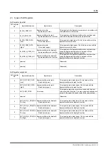
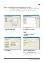
I/O Signal Monitor Function
The "I/O display" and "oscilloscope" functions can be used to check signal status of I/O
inputs/outputs.
I/O Display
This function is used to display the status of hard I/O signals.
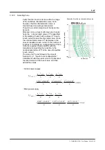
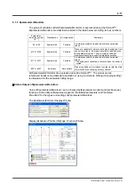
Oscilloscope
The oscilloscope function installed in the utility software can be used to display waveforms of
the #parameters/ #monitor values. The status of the hard I/O and logic I/O signals, velocity
waveforms, position deviation waveforms, etc. can also be captured at the same time. See
Section 8.5.1, "Oscilloscope" for how to use the oscilloscope. This function displays the
input/output status of the hard I/O signals with monitor numbers #310 to #313 and the
input/output status of the logic I/O signals with #314 to #317.