


5-15
TI 71M01D06-01EN 3rd Edition: 2012.12.01
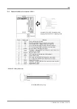
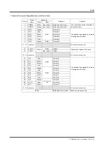
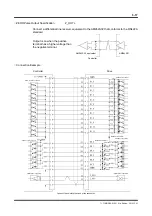
Table of Connector Signal Names and Wire Colors
Pin No.
Signal
name
Wire color
Definition Comment
Color Mark
1 COMP1 White
Blue or black 3
Interface power
Input appropriate power according to
the interface spec.
2 COMN1 Orange
Blue or black 1
Interface power supply -
3 DO_0
Orange
Red 1
I/O output 0
The definition is assigned by the hard
I/O assignment function.
4
DO_1
Gray
I/O output 1
5
DO_2
White
I/O output 2
6
DO_3
Yellow
I/O output 3
7
DO_4
Pink
I/O output 4
8
DO_5
Orange
Red 2
I/O output 5
9 ~ 12 (reserve)
Do not connect any line.
13 Z_OUT+
Yellow
Red 2
Z-pulse +
Outputs the Z-pulse of the motor.
14 Z_OUT-
Blue or black 2
Z-pulse -
15 ~ 18 (reserve)
Do not connect any line.
19 DI_0
Gray
Red 3
I/O input 0
The definition is assigned by the hard
I/O assignment function.
20
DI_1
White
I/O input 1
21
DI_2
Yellow
I/O input 2
22
DI_3
Pink
I/O input 3
23 DI_4
Orange
Red 4
I/O input 4
24
DI_5
Gray
I/O input 5
25
DI_6
White
I/O input 6
26
DI_7
Yellow
I/O input 7
27
DI_8
Pink
I/O input 8
28 DI_9
Orange
Continuous red
line
I/O input 9
29
DI_10
Gray
I/O input 10
30
DI_11
White
I/O input 11
31 ~ 36 (reserve)
Do not connect any line.
Shield
Shield treatment terminal
Make sure to connect this.