


6-1
TI71M01D06-01EN 3rd Edition: 2012.12.01
6. Operation
6.1 Common Basic Functions
6.1.1 I/O Signals
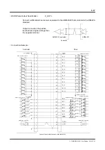
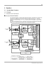
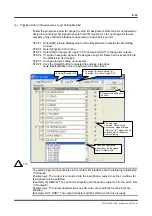
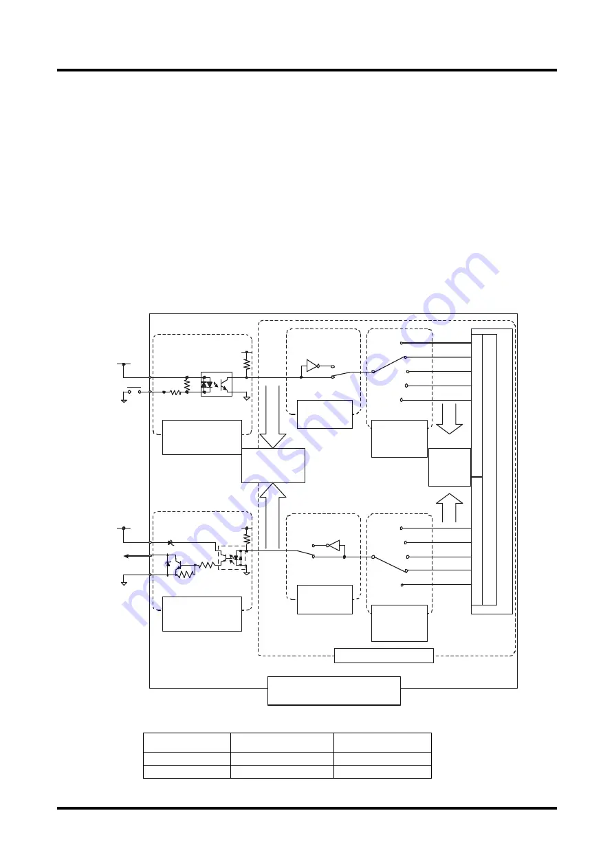
(1) Configuration of I/O Contact Signals
In the case of Contact I/O Interface
The contact I/O signals on CN4 are called physical (hard) I/O, consisting of 12 inputs and 6
outputs. When shipped from the factory, hard I/O is assigned as shown in " Hard I/O
Assignment, Default Settings" in 6.1.1 (4), "Physical (Hard) I/O Assignment, Logic Setting
Method."
Hard I/O can be assigned from any virtual logic contact signal, called logic I/O (48 contact
inputs and 32 contact outputs) (using the hard I/O assignment function).
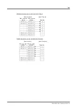
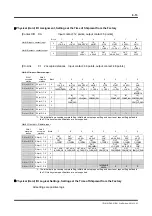
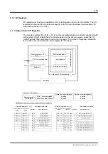
Configuration of I/O Signals
Number of input
points/number of blocks
Number of output
points/number of blocks
Phisical (Hard) I/O
12 points/2 blocks
6 points/1 block
Logic (Soft) I/O
48 points/6 blocks
32 points/4 blocks
"Positive logic"
(Setting at shipment)
"Negative logic"
COMP
I/O input signals,
12 points
Photo-coupler
Hard I/O
assignment
(12 points can
be selected)
Oscilloscope
display of the
signal status
Controller
interface inputs,
12 points
nternal
dri
ve
co
ntro
lle
r
Internal CPU processing
DrvPIII
Photo-coupler
Hard I/O
assignment
(6 points can be
selected)
"Positive logic"
(Setting at shipment)
"Negative logic"
I/O display and
oscilloscope display
of the input/output
signal status
Logic I/O
co
nta
ct o
utpu
ts, 3
2 po
ints
Logic I/O
co
nta
ct in
puts, 48
poin
ts
Hard I/O l
ogical setting
Hard I/O
logical setting
Logic I/O
Controller interface
outputs, 6 points
COMP
COMN
I/O output signals,
6 points