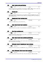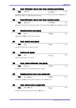
Monitor Description
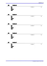
STD1
appendix2‑1
300
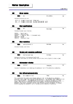
Driver version
Indicates the driver version.
Bit 11‑ 8 Firmware version code Integer part
Bit 7‑ 4 Firmware version code 1st digit below decimal point
Bit 3‑ 0 Firmware version code 2nd digit below decimal point
Unit:
N/A
DriverCode
Hex
301
Motor specifications
Indicates the motor specifications.
Bit31 Type of motor
Bit28‑24 Series of motor
Bit23 1: Absolute Motor 0: Incremental motor
Bit17‑16 Voltage
Bit15‑12 Current
Bit11‑0 Torque and thrust
Unit:
N/A
MotorCode
Hex
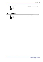
302
Motor resolution
Indicates the motor resolution.
Unit:
pulse/rev pulse/m
MotorRes
Dec
303
Velocity unit conversion coefficient
Indicates the velocity unit conversion coefficient.
This monitor value converts from the internal value of the velocity (digits) to [rps] or [mps].
Unit:
digit/rps digit/mps
VelSense
Dec
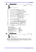
304
Maximum motor velocity
Indicates the maximum velocity based upon the mechanical limit of the motor/drive combination.
Unit:
pulse/sec
Vmax[p/s]
Dec
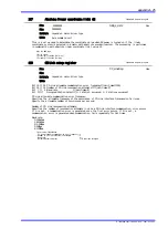
305
User defined maximum velocity
This is defined as the smaller value between mechanical limit of the motor/drive combination
[converted to axis command unit/sec] and the maximum velocity limit parameter [axis command unit/sec]
set in user setting mode. The commanded position velocity is limited by the lesser of the two
values. When executing a trapezoidal motion profile (equal acceleration and deceleration ramps) in
operation mode, the acceleration/deceleration time depends on the acceleration/deceleration
parameters, feed velocity parameter, and the lesser of maximum velocity parameters. A commanded
velocity exceeding the mechanical limit of the motor/drive combination is prohibited.
Unit:
Axis command unit/sec
Vmax
Dec
TI 71M01D06‑01E 2nd Edition : 2007.01.10‑00


