


5-21
TI 71M01D06-01EN 3rd Edition: 2012.12.01
5.10.1
Line Filter
A line filter is effective as a means of suppressing any inverter noise that is conducted back
into the power supply line. Because inverter noise may cause nearby devices to malfunction,
be sure to insert a line filter.
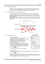
Selecting Line Filter
The switching frequency of the inverter part is 10 kHz. Because inverter noise is caused by
harmonic components when switching, select a line filter with good damping characteristics in
the frequency band of 100 kHz to 1 MHz.
(Line filters with common mode coils of 5 mH or more)
Please use the recommended line filter or an equivalent product.
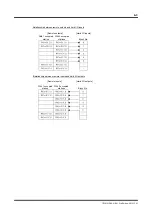
Obtaining Current Capacity
Please see Section 5.11, "Drive Input Current."
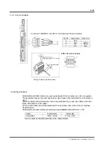
Mounting Filter
Secure the filter to a metal plate. If rust proofing is required for the metal plate, apply
electrically conductive plating. If the filter has to be mounted on a coated surface, be sure to
remove the coating before mounting the filter. (The same holds for the mounting surface of
the drive.)
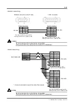
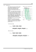
If you connect the wires for filter inputs and outputs, the noise will transfer between the wires
and the effect of the filter will be lost. Be sure the wires are kept separate.
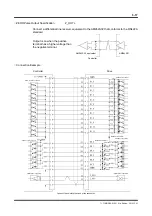
Power supply side
Load side
Bundling
Power supply side
Load side
Bundling
Bundling