


5-9
TI 71M01D06-01EN 3rd Edition: 2012.12.01
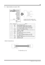
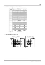
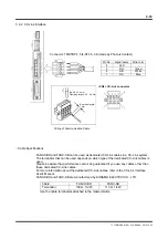
5.6 Serial Interface Connector <CN1>
Pin No.
Signal name
Definition
1 FG
Frame
GND
terminal (Shield)
2
RxD
RxD terminal RS232C single channel communication
3
TxD
TxD terminal RS232C single channel communication
4
A
Rx (+) side terminal RS485 multi-channel communication
5
Y
Tx (+) side terminal RS485 multi-channel communication
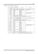
6
485SW
Busy condition bit RS485 multi-channel
7 TRMP
Terminator terminal RS485 multi-channel communication (short
circuited to #14 TRMN)
8
CN1SW
Busy condition bit CN1
9
+5V
+5V power (operation display panel and pendant)
10
SG/LG
Signal GND terminal
11
B
Rx (-) side terminal RS485 multi-channel communication
12
Z
Tx (-) side terminal RS485 multi-channel communication
13
SG/LG
Signal GND terminal
14 TRHN
Terminator - terminal RS485 multi-channel communication (short
circuited to #7 TRMP)
15
SG/LG
Signal GND terminal
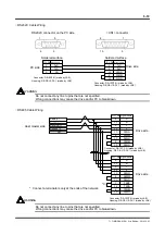
RS232C Cable (Optional)
C1P-ENN-2276-020 (2.0 m)
Connector: DA-15PF-N (made by JAE)
Housing: DA-C8-J10-F4-1 (made by JAE)