


appendix1‑9
38
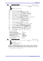
Error process setup register 1
Defines settings for valid/invalid and error treatment when an error occurs in the following list. The
top bit is to set valid/invalid, and the last 3 bits represent error processing code in each area.
Invalid setting is unavailable for excessive position command differential error (Invalid setting (0)
is not effective).
Valid/Invalid setting bit
0: Invalid 1: Valid
Error processing code
0: Servo ON sustaining after deceleration and stop
1: Servo OFF after deceleration and stop
2: Servo ON sustainnig after immediate stop
3: Servo OFF after immediate stop
4: Servo OFF immediately
Bit 31 ‑ 28 Over speed
Bit 27 ‑ 24 Overload
Bit 23 ‑ 20 Excessive position error
Bit 19 ‑ 16 Excessive commanded position differential value
Bit 15 ‑ 12 Tandem error (Slave drive error)
Bit 11 ‑ 8 Coordinate error A
Bit 7 ‑ 4 Bus voltage dropping
Bit 3 ‑ 0 AC mains power supply voltage error
−
−
depend on motor.driver type
Min:
Max:
Initial:
Unit:
Initial value: HAAAABA2A
Over speed : Valid, Servo ON sustainnig after immediate stop
Overload : Valid, Servo ON sustainnig after immediate stop
Excessive position error: Valid, Servo ON sustainnig after immediate stop
Excessive commanded position differential value:
Valid, Servo ON sustainnig after immediate stop
Tandem error : Valid, Servo OFF after immediate stop
Coordinate error A : Valid, Servo ON sustainnig after immediate stop
Bus voltage dropping : Invalid, Servo ON sustainnig after immediate stop
AC mains power supply voltage error:
Valid, Servo ON sustainnig after immediate stop
ErrorReg1
Hex
39
Error process setup register 2
Defines settings for valid/invalid and error treatment when an error occurs in the following list. The
top bit is to set valid/invalid, and the last 3 bits represent error processing code in each area.
Valid/Invalid setting bit
0: Invalid 1: Valid
Error processing code
0: Servo ON sustaining after deceleration and stop
1: Servo OFF after deceleration and stop
2: Servo ON sustainnig after immediate stop
3: Servo OFF after immediate stop
4: Servo OFF immediately
Bit 31 ‑ 28 + direction hardware End of Travel (EOT) limit
Bit 27 ‑ 24 ‑ direction hardware End of Travel (EOT) limit
Bit 23 ‑ 20 + direction software End of Travel (EOT) limit
Bit 19 ‑ 16 ‑ direction software End of Travel (EOT) limit
Bit 15 ‑ 12 (reserved)
Bit 11 ‑ 8 Monitor pulse output error・CC‑Link Error
Bit 7 ‑ 4 Interface emergency stop
Bit 3 ‑ 0 (reserved)
−
−
depend on motor.driver type
Min:
Max:
Initial:
Unit:
Bit 11‑8 is effective at an CC‑Link I/F.
Initial value: H2222*$b* (*: unfixed) ($ :It is dependent on an interface)
(+)direction hardware EOT : Invalid, Servo ON sustainnig after immediate stop
(‑)direction hardware EOT : Invalid, Servo ON sustainnig after immediate stop
(+)direction software EOT : Invalid, Servo ON sustainnig after immediate stop
(‑)direction software EOT : Invalid, Servo ON sustainnig after immediate stop
CC‑Link Error : Only for CC‑LinkI/F, Servo ON sustainnig after immediate
stop
Interface emergency stop : Valid, Servo OFF after immediate stop
ErrorReg2
Hex
TI 71M01D06‑01E 2nd Edition : 2007.01.10‑00