


4-5
TI 71M01D06-01EN 3rd Edition: 2012.12.01
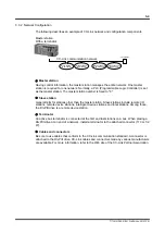
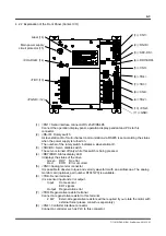
4.2.3 Explanation of the Front Panel (CC-Link)
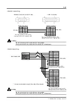
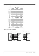
(1) <CN1> Serial interface connector RS 232C/RS485
Connect the operation display panel, operation display pendant and PCs to this
connector.
(2) <RS-ID> Rotary switch
A slave station ID of multi-channel communication via RS485 is set according the status
when the power supply is turned on.
The number of the rotary switch indicates a slave station ID.
(3) <SRV-DS> Servo disable switch
The servo is turned off only while this switch is being pressed.
(4) <RDY/ERR> Status display LED
It displays the status of the drive.
Green: RDY No
error
Red:
ERR Error occurred
(5) <CN3>
Analog
monitor
connector
It is possible to observe torque and velocity waveform with an oscilloscope. The analog
monitor card (optional, part number R7041WC) is available.
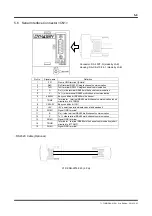
(6) <TB4> Sensor terminal
It is a sensor input and error output.
Input Home sensor
EOT
signals
Output Regeneration error
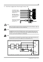
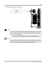
(7) <TB3> Regenerative resistor terminal
Connect a regenerative resistor to this terminal.
External regenerative resistors will be required if you rotate the motor with external
force (please consult us separately).