Appendix 3-2
TI71M01D06-01EN 3rd Edition: 2012.12.01
Name
Error
code
Recovery
Cause and condition detected
Action taken
at occurrence
Countermeasure
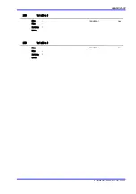
ABS encoder error
Excessive detection error
14.1
Not
possible
Abnormal absolute position signal was detected.
Inappropriate configuration (matching with motor)
Initial
processing
not completed
Execute the same
countermeasure for the error
14.3.
Correct configuration.
Excessive velocity at
detection
14.2
Motor moves when the power was turned on.
Abnormal resolver signal was detected.
Turn on the power while motor
is stopped.
Execute the same
countermeasure for the error
14.3.
SIG0 1X signal error
14.3
Abnormal resolver signal was detected.
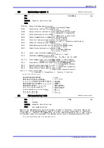
Contact failure or damage of connector
Breaking of wire
Irruption of noise into encoder/resolver cable
Malfunction of motor
Malfunction of drive
Repair or replacement of
connector
Replacement of cable
Denoising or re-configuration
of wiring upon checking
source of noise
Put apart encoder-resolver
cable from electric power line
or high frequency line
Change of grounding of shield
Shortest encoder cable
Note: Be careful not to deforming
or damaging contact section
by tester equipment when
checking conduction of cable.
Replacement of motor
Replacement of drive
SIG0 NX signal error
14.4
Linear coordinate range
error
14.5
Motor position when the power is turned on was
out of coordination range set by #116, Limit of
absolute linear coordination 1 and #117, Limit of
absolute linear coordination 2
Re-set motor position when
the power is turn on so that it
can be within the coordination
range.
Change value(s) of limit of
absolute linear coordination
range.
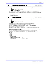
Encoder error
SIG0 edge disengaged
15.1
Not
possible
An error was detected in an encoder/resolver
signal.
Contact failure or breakdown of a connector
Cable disconnection
Noise is generated in an encoder/resolver cable.
A problem inside the motor
A problem in the drive
* Check the conductivity of the cable by using a
tester. The contact area must not be deformed
or damaged.
Servo OFF
Check the connector section,
repair or replace if necessary.
Replace the cable.
Eliminate the noise
generating source, and
review the wiring route.
Replace the motor unit.
Replace the drive.
SIG1 edge disengaged
15.2
SIG0 cycle error
15.3
SIG1 cycle error
15.4
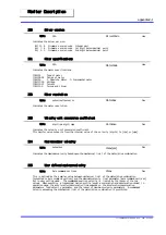
Coordinate system error A
Eccentric compensation
error
16.1
Not
possible
It was detected that the slit plate deviated from the
center and exceeded the allowable eccentric
volume in a DM series motor unit (except
DM1B-004/006, DM1C-004).
A moment load was applied to the rotation
section.
A support and cable made contact with the
hollow hole and therefore force was applied.
A substantial impact was applied to the motor.
An abnormal encoder signal was generated.
* A low velocity (0.05rps or less) was used for
detection.
Error setup
register 1
dependent,
bits 11 to 8
Remove the load, and also
remove the one that is giving
force.
Adjust the support and cable
so that they are not in contact
with the hollow hole.
Repair the motor unit if an
error occurs while in the
no-load state.
Check the items pertaining to
the encoder errors.
Coordinate system error B
Outside of command
coordinate area
17.2
Possible
The setup value to be used for coordinate system
operation (coordinate value setting) was less than
0 or more than the scaling command unit value
when the rotation coordinate system was used.
None in
particular

