


6-113
TI71M01D06-01EN 3rd Edition: 2012.12.01
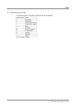
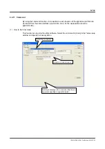
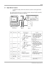
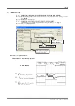
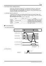
(1) Parameter
Setting
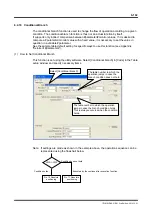
STEP 1 Select the [#parameter] from [Data Management] in the utility software.
STEP 2 Select the Signal Monitor Terminal tab and select a terminal whose setting you want
to change.
STEP 3 Select a monitor signal.
STEP 4 Adjust the monitor gain (except for digital monitor signals).
* At this point, the output range relative to the gain setting is displayed.
STEP 5 Click the [Regist] button.
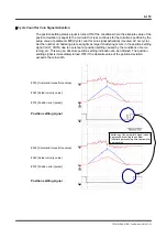
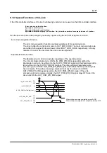
<Example of output waveform>
Output waveform at positioning operation
Set the monitor signal
and monitor gain.
The input range is displayed.
Select the monitor signal
you want to monitor.
VEL speed waveform
AM1 #372
[Position error (pulse)] waveform
DM1 #320
[Status register #3, bit 12 operation
being executed] waveform
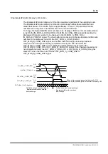
AM2 #325
[Command current value] waveform