


7-4
TI71M01D06-01EN 3rd Edition: 2012.12.01
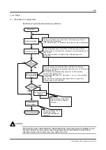
7.2.2 Filters
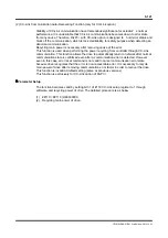
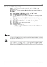
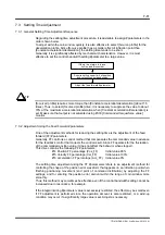
(1) Procedure for Tuning Filters
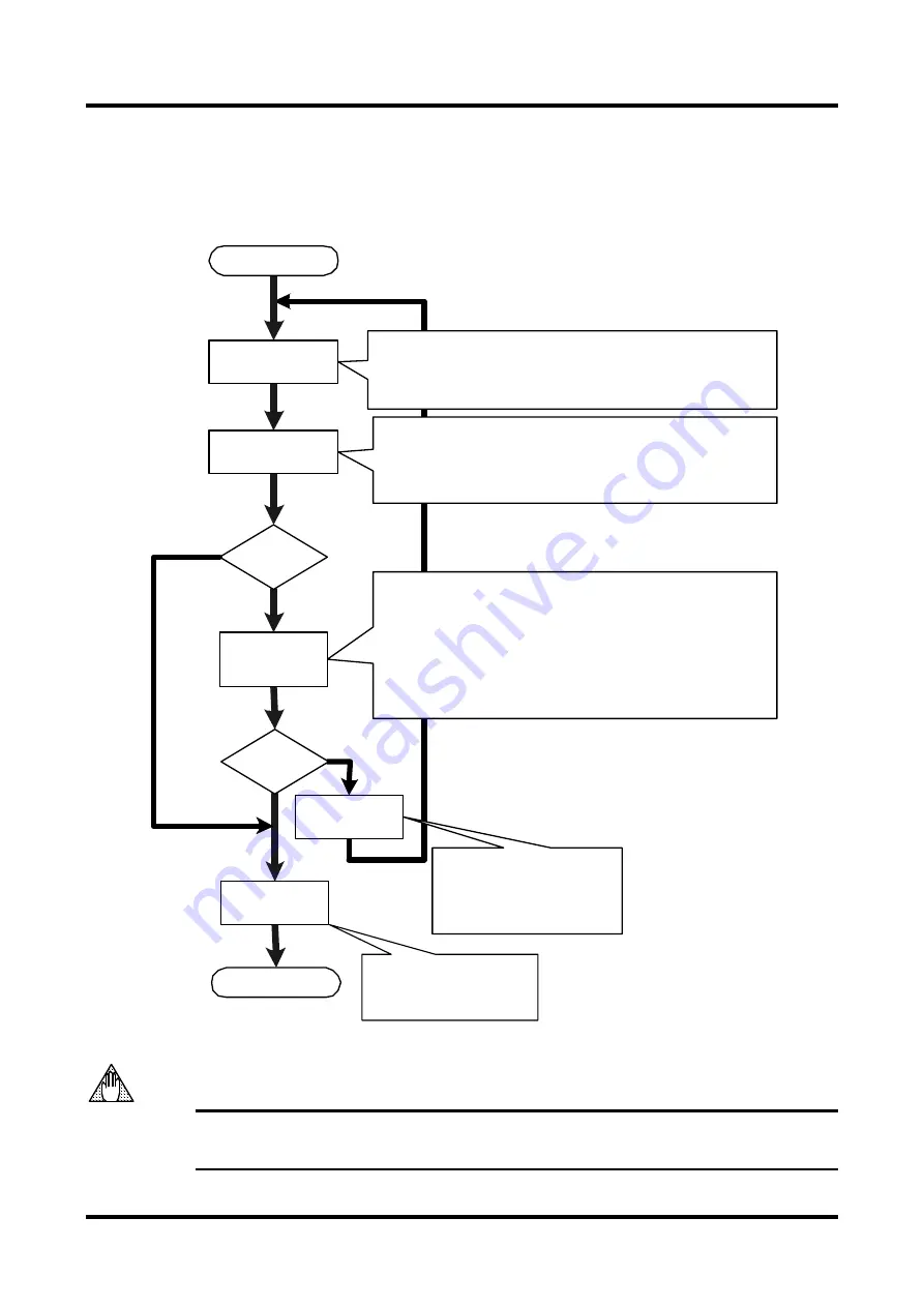
Set filters using the flowchart below as reference.
If the setting of the control system is inappropriate, the motor may begin to oscillate or even
become unstable in some cases. Take enough precautions with respect to the motor's
operation range and its safety when you adjust the servo.
YES
NO
NO
YES
CAUTION
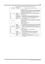
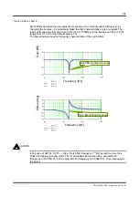
Set the notch frequency of notch filter 2 to the frequency at which
vibration noise is minimized if the resonance is not eliminated by notch
filter 1 alone.
Note: Set notch filter 2 to "Disable" if the vibration noise is not
decreased.
Adjust notch filter 1
Adjust the phase
lag compensation
filter
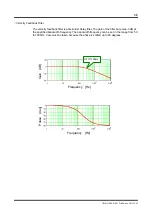
Set the notch frequency of notch filter 1 to the frequency at which
vibration noise is minimized.
Note: Set notch filter 1 to "Disable" if the vibration noise is not decreased.
Adjust notch filter 2
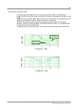
Set the phase lag compensation filter according to the following
standards: #24 [First lag compensation frequency #1] = n x #2 [Velocity
control bandwidth #1]
#25 [First lag compensation frequency #2] = 4 x #24 [First lag
compensation frequency #1]
Set parameter #24 with n = 3. Set it with n = 2 or n =1 if the vibration
does not stop.
Note: Set the first-order lag compensation filter to "Invalid" if the
vibration noise is not decreased.
Was
the resonance
suppressed?
Lower the servo
stiffness
Decrement the current setup
value of #1 [Servo stiffness
setup] by 1.
End filter adjustment
Readjust the
servo stiffness
Adjust filters
Was
the resonance
suppressed?
The servo stiffness may be
increased by taking
countermeasures against
resonance.