


5-19
TI 71M01D06-01EN 3rd Edition: 2012.12.01
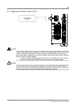
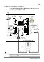
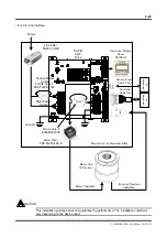
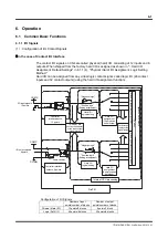
5.10 Noise Prevention and Installation Conditions
A CE Declaration of Conformity (declaration) regarding EMC has been made for the DrvPIII
drive under the following installation conditions.
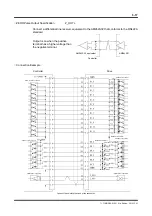
For Contact I/O Interface
This installation guideline does not guarantee the performance. The installation conditions
vary depending on the device used.
CAUTION
Operation Display
Panel
PC100G3
Motor Filter
FHF-TB/30/250-S
Motor Unit
(DR series)
Power
DrvPIII
4kW
Drive
Motor Cable(6m)
Line Filter
FN351-16/29
Main Power Cable
Control Power
Cable
Ground
Controller
Cable(3m)
Encoder/Resolver
Cable(6m)
Sensor/Alarm
Cable(1.2m)
Mounted on an Aluminum Plate
Ferrite Core 1
ZCAT3035-1330
Ferrite Core 2
E04SR401938
SEIWA
Te
rm
in
at
in
g
jig
Te
rm
in
at
in
g
jig