


Appendix 3-4
TI71M01D06-01EN 3rd Edition: 2012.12.01
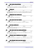
Name
Error
code
Recovery
Cause and condition detected
Action taken
at occurrence
Countermeasure
Overload
Motor coil line overload
22.1
Possible
The power-squared duty is calculated from the
current command value, but it exceeded the
designated value.
Perform current control without monitoring setting.
Limited current when the value became lower than
the cancellation current-squared duty value.
Error setup
register 1
dependent,
bits 27 to 24
Current
control was
executed
regardless of
its setting.
Review the operation cycle.
Set a longer
acceleration/deceleration
time.
Eliminate an external force
that is constantly being
applied.
The current-squared duty can be
checked by #386.
Heat
sink
over-heat
22.2
Detected a heat generation of 85
C or more inside
the drive.
Limited current while detecting, and cancelled it
when not detecting.
Check the ambient temperature
and installation environment of
the drive.
Excessive position deviation
23.0
Possible
The position deviation exceeded the user setup
value when position control was executed.
Acceleration/deceleration time is too short.
Servo tuning failure
Error setup
register 1
dependent,
bits 23 to 20
Set a longer
acceleration/deceleration
time.
Perform a servo tuning again,
and set an appropriate value.
Eliminate an external force
that interferes with the
motor's rotation.
Over-speed 24.0
Possible
The absolute value of the current velocity value
detected from SIG0 was more than the maximum
velocity of the motor.
The velocity exceeding the monitor #305 value
was detected.
Error setup
register 1
dependent,
bits 31 to 28
Set a longer
acceleration/deceleration
time.
Perform a servo tuning again,
and set an appropriate value.
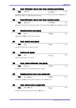
Regeneration error
If a regenerative resistor is
not installed, install one.
If this error occurs when a
regenerative resistor is
already installed, review the
acceleration/deceleration
time and the operation
cycle.
The motor unit is rotated by
an external force.
Regenerative resistor
over-load
25.1
Not
possible
Excessive electric power was applied to a
regenerative resistor, and thus the allowable
electric power of the regenerative resistor was
exceeded.
Servo Off
Regeneration
error output
Regeneration FET
over-load
25.2
Excessive electric power was applied to a
regeneration FET, and thus the allowable electric
power of the regeneration FET was exceeded.
Regeneration
circuit
error
25.3
The RGN_FET status and RGN_ANS status
sampled at every msec were verified at every
32msec. This error occurred when a difference
exceeding 2 digits was detected in each on-duty.
Servo not ready
30.0
Possible
The Servo OFF state occurred during an axis
operation by internal control, or during an axis
operation by an external position command.
Servo OFF
Check the wiring, power
supply and PLC software so
that the IN_SERVO signal
does not change during an
operation.
Execute an axis operation
command after turning the
servo on.
Excessive position command
differential value
31.0
Possible
Attempted to execute an axis operation at a
velocity exceeding the maximum motor velocity set
by the user during an axis operation by internal
control, or during an axis operation by an external
position command.
If the number of commanded pulses per 1msec
exceeds the rate of maximum command
frequency, the excessive position command
differential value error (31.0 for error code)
appears.
Error setup
register 1
dependent,
bits 18 to 16
Set maximum rate of pulse input
so that it is less than the speed
monitored by #305 (Maximum
speed).
Set the commanded speed from
controller lower so that the pulse
input rate does not reach the
maximum
command frequency.
(If the pulse output frequency of
controller is unstable, it is
impossible to command pulses at
the maximum
command frequency.)
+ direction hardware EOT
42.0
Possible
A + direction EOT signal was detected during an
axis operation by internal control, during an axis
operation by an external position command, or
while moving in the + direction.
Error setup
register 2
dependent,
bits 31 to 28
Reduce the amount of
movement so that it does not
exceed the hardware EOT
sensor.
Change the conversion of
pulse units.
Is the sensor operating
normally? Is any noise
generated on the sensor
power supply?
Check the wiring connection
of the sensor.
- direction hardware EOT
43.0
Possible
A - direction EOT signal was detected during an
axis operation by internal control, during an axis
operation by an external position command, or
while moving in the - direction.
Error setup
register 2
dependent,
bits 27 to 24