


6-2
TI71M01D06-01EN 3rd Edition: 2012.12.01
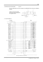
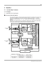
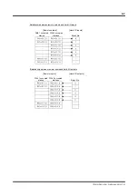
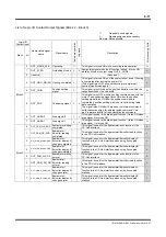
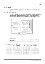
In the case of CC-Link Interface
Remote I/O at the CC-Link master station is called hard I/O on the drive. The number of
contact I/O varies with the number of stations occupied (see the table below).
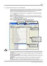
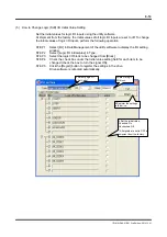
When shipped from the factory, hard I/O is assigned as shown in " Hard I/O Assignment,
Default Settings" in 6.1.1 (4), "Physical (Hard) I/O Assignment, Logic Setting Method."
Hard I/O can be assigned from any virtual logic contact signal, called logic I/O (48 contact
inputs and 32 contact outputs) (using the hard I/O assignment function).
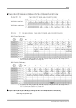
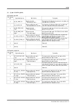
Configuration of I/O Signals
Number of input
points/number of blocks
Number of output
points/number of blocks
Physical (Hard) I/O
With 1 occupied station
16 points/2 blocks
16 points/2 blocks
With 2 occupied stations
48 points/6 blocks
48 points/6 blocks
Logic I/O
48 points/6 blocks
32 points/4 blocks
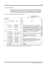
Remote output
RY (n+*).*
CC-Link
interface chip
Remote input
RX (n+*).*
DrvPIII
"Positive logic"
(Setting at shipment)
"Negative logic"
Hard I/O
assignment
(16 or 48 points
can be selected)
Oscilloscope
display of the
signal status
Inte
rnal drive con
tr
oller
Internal CPU processing
Hard I/O
assignment
(16 or 48 points
can be
"Positive logic"
(Setting at shipment)
"Negative logic"
I/O display and
oscilloscope display
of the input/output
signal status
Logic I/O
co
nta
ct o
utpu
ts, 3
2 po
ints
Logic I/O
co
nta
ct in
puts, 48
poin
ts
Hard I/O
ogical setting
Hard I/O
logical setting
Logic I/O