


6-111
TI71M01D06-01EN 3rd Edition: 2012.12.01
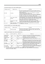
Parameters Related to the Position Settling Signal
Parameter number
Parameter name
Description
#90 ~ #97
Coin width
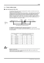
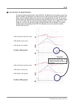
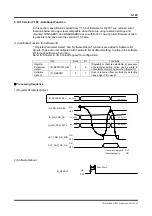
The OUT_COIN signal is turned ON when the position deviation is within the
setup value range of this parameter. Set this parameter according to the required
accuracy of the device.
While performing table data operation, the coin width set by the parameter
selected at creating table data becomes valid.
Under other conditions, the coin width is set by entering a coin width number in
IN_POSW.0 to IN_POSW.2 as a binary value. This means that if IN_POSW.0 to
IN_POSW.2 are all turned OFF, the setup value of #90 is selected.
#28
Actual position value filter
frequency
This parameter is valid only when the current position value filter is set to valid in
system setup register 2. The current position value is filtered by a linear low-pass
filter. This parameter is used for the purpose of preventing chattering of the COIN
signal. Using the filter does not cause any changes to the motor operation, but
may cause the output of the OUT_COIN signal to be delayed.
#29
Cycle count for coin signal
activation
This parameter is used to prevent chattering of the OUT_COIN signal.
The position settling status signal is turned ON if the position deviation is in the
range set by the coin width for duration of (setup value of #29) x 1 [msec].
#110 bit17
System setup register 1, settling
width unit pulse selection
This parameter selects the unit of the settling width set by the parameter.
0: Command unit, 1: Pulse unit
Monitors Related to the Position Settling Signal
Parameter number
Parameter name
Description
#372
Position error (pulse)
This monitor monitors the amount of position deviation. The pulse position
deviation is the value obtained by subtracting the current pulse position value
from the pulse position command value.
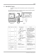
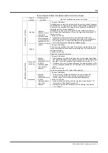
Inputs/Outputs Related to the Position Settling Signal
Name
Logic I/O
Hard I/O
Monitor (*2)
Description
Position settling
status output
(OUT_COIN)
Block2
Bit4
CN4-8
#320 status register
1, bit 16
This output is turned ON when the position deviation is within the
setup range. It is turned ON as far as the position deviation is in the
setup range, even if the motor is still operating.
Positioning status
output
(OUT_POS)
Block2
Bit5
(*1)
#320 status register
1, bit 17
The positioning status refers to the status in which no
acceleration/deceleration operation is being performed to move the
motor.
Busy signal
(OUT_BUSY)
Block0
Bit6
CN4-5 ---
This signal turns ON during table data operation and jog movement.
If the position coin waiting function is set to "enable" in table data, the
OUT_BUSY signal turns OFF after the position of the motor settles.
Operating
(OUT_MODE_EXE)
Block2
Bit0
(*1)
#320 status register
1, bit 12
This signal turns ON during table data operation (when an operation
started with IN_START is being executed). If the position coin
waiting function is set to "valid" in table data, the OUT_MODE_EXE
signal turns OFF after the position of the motor settles.
Axis operating
OUT_AXIS_EXE
Block0
Bit3
(*1)
#320 status register
1, bit 10
This signal turns ON while the motor is operating. If the position coin
waiting function is set to "valid" in table data, the OUT_AXIS_EXE
signal turns OFF after the position settles.
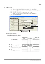
*1: The status can also be checked with the Axis Signal Monitor, Parameter Monitor and Oscilloscope
functions of the utility software.