


5-25
TI 71M01D06-01EN 3rd Edition: 2012.12.01
21
I
22
I
p
I
2
22
t
cy
t
2
2
N
21
t
11
I
12
I
p
I
1
12
t
cy
t
1
1
N
11
t
(max)
p
I
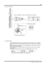
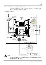
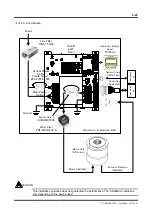
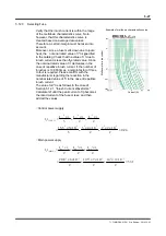
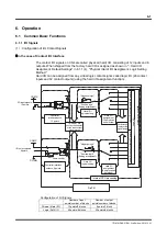
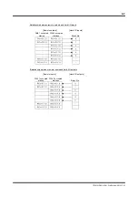
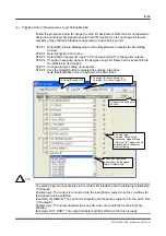
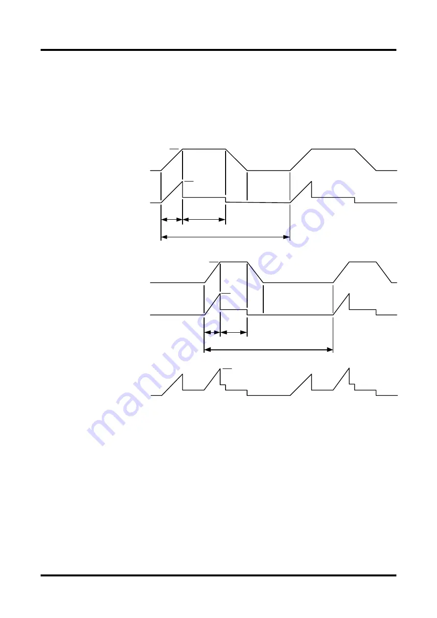
5.11.2 How to Obtain Input Current When Operating Multiple Drives
If multiple drives are to share one circuit breaker and line filter, obtain the effective input
current for each drive from the motor operation pattern and add all the values to obtain the
required rated current.
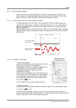
Obtain the effective input current
l
1in (rms)
,
l
2in (rms)
and so on of each drive from the motor
operation pattern using the procedure in Section 5.12.1, "How to Obtain Input Current."
Obtain the total current of each drive input current,
l
in (rms)
, and then select a circuit breaker
and line filter that satisfy this value.
I
in(rms)
= I
1
in(rms)
+ I
2
in(rms)
+
…
Be sure to verify that the value of the maximum current of the combined drive input current
l
p
(max)
is within the operation characteristics curve for the selected circuit breaker and fuse.
Motor 1 Operation pattern
Velocity waveform
Input current
Acceleration
Constant velocity
(maximum velocity)
Deceleration
Stop
Cycle time
Acceleration
Motor 1 + motor 2
Combined input
current
Motor 2 Operation pattern
Velocity waveform
Input current
Acceleration
Constant velocity
(maximum velocity)
Deceleration
Stop
Cycle time
Acceleration