


7-15
TI71M01D06-01EN 3rd Edition: 2012.12.01
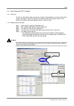
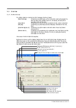
7.4.3 Usage Example of the FFT Function
Estimation of Resonance Frequency
The servo stiffness can be improved by estimating the resonance frequency and setting the
optimum filter.
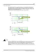
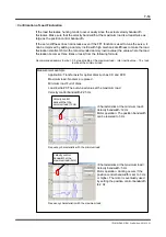
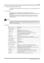
The gain at the resonance point
is attenuated by the notch filter
Velocity bandwidth: 50 Hz
Mechanical resonance point
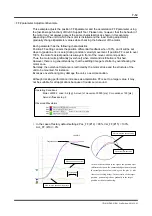
<Characteristics before tuning>
Velocity bandwidth: 50 Hz
Filter: None
Motor condition: The motor oscillates with
high frequency noise when it is operated.
The oscillation noise is not stopped
unless the velocity bandwidth is lowered
to 20 to 30 Hz.
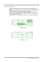
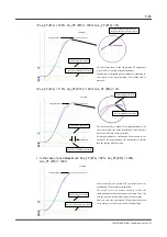
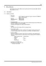
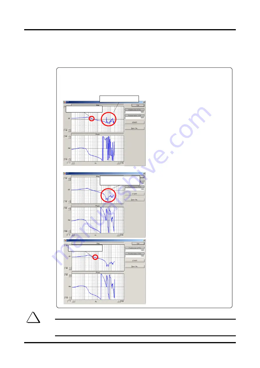
<Characteristics after filter setting>
Velocity bandwidth: 50 Hz
Filter:
Notch filter 1: 450 Hz
Notch filter 2: 1200 Hz
Motor condition: The motor does not
oscillate and operates steadily.
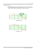
<Characteristics after tuning>
Velocity bandwidth: 80 Hz
Filter:
Notch filter 1: 450 Hz
Notch filter 2: 1200 Hz
Motor condition: The motor does not
oscillate and operates steadily.
The settling time was reduced to
approximately half of that before
adjustment.
Velocity bandwidth: 80 Hz
<Measurement example>
Application: Index table of semiconductor chip parts
Problem: Since the index table is thin, it resonates and the servo stiffness does not
increase.
Note that inserting filters cause a phase shift in the closed loop. After adjusting the filters,
operate the motor and confirm that the velocity waveform does not vibrate using the
oscilloscope function.
TIP