


6-47
TI71M01D06-01EN 3rd Edition: 2012.12.01
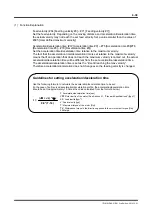
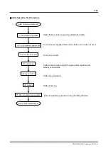
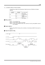
Servo ON Operation
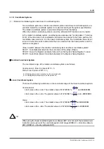
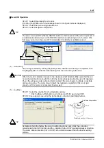
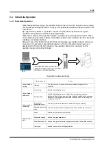
STEP 1 Select [Operation] from Control.
(Click the [Yes] button when the message shown in the figure below is displayed.)
STEP 2 Select the Auto-tuning operation tab.
STEP 3 Select the [Servo-ON] button.
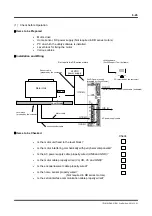
The servo is turned OFF while the SRV DS switch on the front panel of the drive is pressed. It
is advisable to place a finger on the SRV DS switch when instructing to turn the servo ON;
that way, you can turn the servo OFF immediately if instability or oscillations occur.
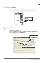
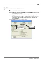
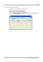
(4) Auto-tuning
Auto-tuning is started by clicking the [Drive] button. After the auto-tuning is completed, click
the [Regist] button to write the data resulting from the auto-tuning to the drive.
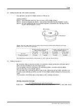
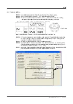
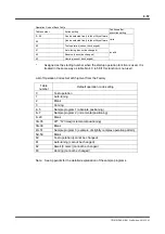
When the motor is started, it moves in the clockwise (CW) direction. Make sure that there is
no mechanical interference with the rotor (the rotor swings approximately up to 30 degrees).
Check the wiring (encoder cable and motor cable) if the motor begins to vibrate or oscillate
during auto-tuning. The motor may vibrate if it is installed on a platform that is not rigid
enough, or if the motor is not securely fixed as well.
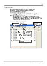
(5) Jog
Move
STEP 1 Select the Jog tab from the Operation window.
* Click the [Servo-ON] button to turn the servo ON if it was turned OFF.
STEP 2 Execute jog move using the [+ direction], [- direction] and [Stop] buttons.
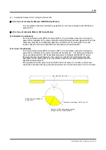
At shipment from the factory, the motor rotation direction is set so that the + direction
corresponds to the CW direction and the - direction to the CCW (counterclockwise) direction.
The motor rotation direction (CW or CCW) is the direction viewed from the load mounting
surface.
TIP
Execute auto-tuning.
3 Select the
[Servo-ON] button.
2 Select the
Auto-tuning
operation tab.
CAUTION
TIP
CW
Rotation direction of the motor
CW
CCW
Load mounting surface