Stratasys uPrint Service Manual Download Page 354

uPrint/uPrint SE Service Manual

7-11


Figure 7-411: Remove the tips

D. 

Repeat for second tip if necessary.

Installing tips

1.

Place the tip shield on the tip. Be sure to install the proper tip. See 

Figure 7-412.

Figure 7-412: Tip shield alignment

2.

With gloved hand, insert the new tip into the heater block. 

3.

Use needle nose pliers to grasp the stainless steel shield of the tip. 

4.

Pull the tip shield toward you, then lift up to install the tip. 

5.

Push the tip toward the back of the printer once it is all the way up against the heater 

block. 

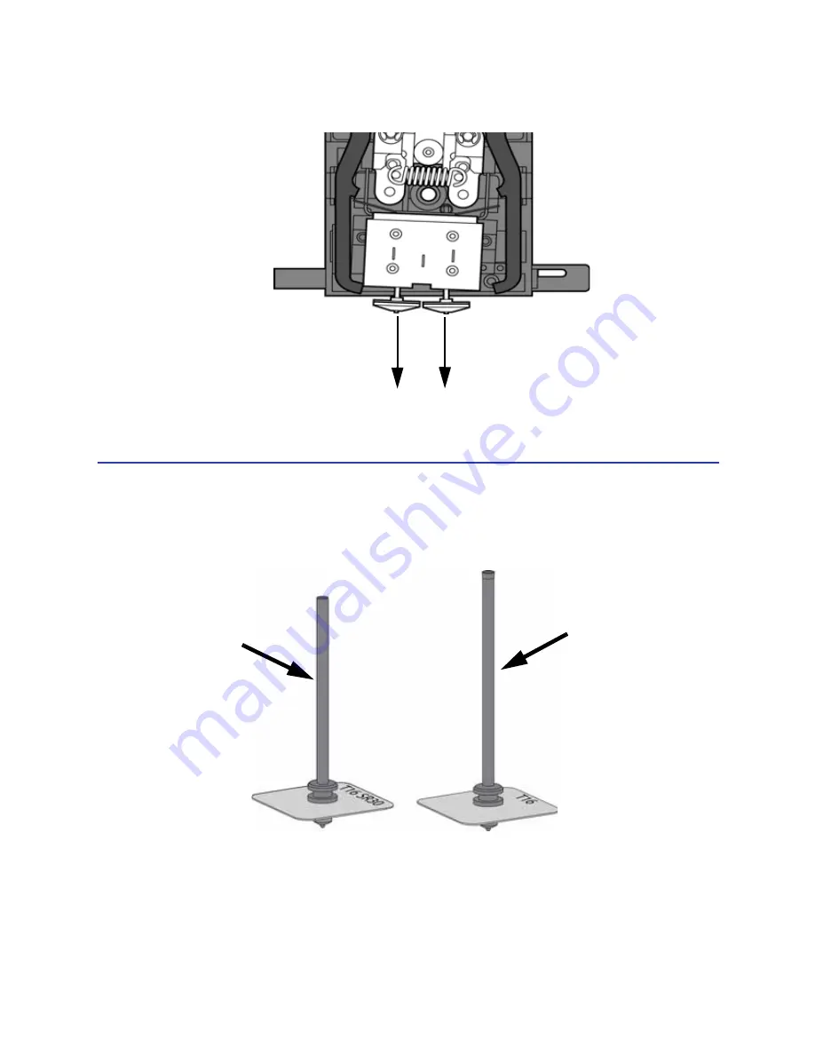
Pull tips down to remove

Shorter tube 
Imprinted with “T-16 

SR30”

Liquefier tubes

Longer tube
Imprinted with “T16”

Summary of Contents for uPrint

Page 1: ...uPrint and uPrint Plus uPrint SE and uPrint SE Plus Service Manual Part No 209010 0001 Rev D...

Page 2: ...served Stratasys Dimension uPrint Catalyst FDM Dimension BST Dimension SST WaveWash and Ecoworks are registered trademarks of Stratasys Inc FDM Technology Fused Deposition Modeling ABSplus Catalyst EX...

Page 3: ...he PDF application as hyperlinks Click on the headings and page numbers in the Table of Contents to go to a specific page or chapter Click on italicized text which are cross references to figures head...

Page 4: ...2 7 Material Motor Control ________________________________________________ 2 7 Temperature Control__________________________________________________ 2 7 Liquefier Temperature Control _______________...

Page 5: ...Status__________________________________________________________ 3 7 Versions ______________________________________________________________ 3 8 Travel Limits_________________________________________...

Page 6: ...ibution I O Card ______________________________________________ 4 29 Power Distribution Board PDB ___________________________________________ 4 31 Hard Drive __________________________________________...

Page 7: ...Part Based calibration________________________________ 5 7 Tensioning the X Y Drive Belts ______________________________________________ 5 37 Get Send Calibration Files _______________________________...

Page 8: ..._________________________________________ 6 52 Part fell over ____________________________________________________________ 6 53 Part shifting __________________________________________________________...

Page 9: ...____________ 8 11 Material Bay ________________________________________________________________ 8 12 Cables _____________________________________________________________________ 8 13 Checklists ______...

Page 10: ...vated if any thermal limit switches trip Thermal snap switch located on the Head Board Main thermal fuse Caution Indicates a potentially hazardous situation which if not avoided may result in minor or...

Page 11: ...1 2...

Page 12: ...ier Temperature Control __________________________________ 2 8 Actuators Switches Optical Sensors___________________________ 2 9 Safety Devices_________________________________________________ 2 9 Con...

Page 13: ...l show Idle no part in the queue or Ready to build followed by the part name Once a part is started the appropriate liquefier will begin to heat Once the liquefier and chamber reach the operating temp...

Page 14: ...ER to the display the carriers are unlatched and the unit waits for you to respond If there are no carriers in the printer when the material button is pushed or if an unload has just been completed th...

Page 15: ...tion commands that the controller will execute to build the model 4 System completes substrate measurement 5 Z stage moves to bottom of Z travel 6 Head moves over the purge bucket and prepares to buil...

Page 16: ...ice Manual 2 5 Electronics Overview Figure 2 1 Electronics Overview detail PDB Controller Board SBC AC Input 5 and 12 VDC Power Supply Support heater 120 VDC power supply 24 VDC power supply 120 240 V...

Page 17: ...ble or SATA cable The HDD contains the Linux operating system and all the control software needed to run the system except the controller firmware This is also where all the downloaded models are stor...

Page 18: ...back to the SBC X Y Z Axis Control The controller takes the flow rate information from the SBC and sends it to the PMD processor The PMD 2840 processor services the X and Y stepper motors and the mod...

Page 19: ...tion this signal is biased The lowest reading possible is 109 5 C The highest reading is 330 C The liquefier temperature is maintained at Model 310 C Support 300 C Temperature control is accomplished...

Page 20: ...ay encryption board The material encryption board in turn connects to the e prom on the carrier spool via two pogo pins The controller board monitors these switches Z limit switches upper and lower X...

Page 21: ...ing the board system power must be cycled before building The reset button should only be used after using TeraTerm Dip Switches There are three dip switch banks SW2 SW5 SW6 located on the top right s...

Page 22: ...LEDs There are 11 LEDs located on the controller board A grouping of three D1 D3 are located on the lower left side The other group of eight D6 D13 are located on the upper right side D1 D3 are lit wh...

Page 23: ...nsor not used F J9 Z motor G J10 I O board connection H J11 I O board connection I J7 24VDC input J Test points and LEDs see detail in this section K J4 5 12VDC input L Voltage indicator LEDs see deta...

Page 24: ...ans and chamber lights The 120 VDC circuit powers the model heater and a separate 120 VDC supply powers the support heater There are two fuses on the power distribution board Fuse F1 fuses the AC inpu...

Page 25: ...nd head thermostat snap switches 5 VDC if both switches closed Normal tp17 lo tp19 hi ch thermostat fault tp17 lo tp19 lo Head TC Alarm TP26 High if head T C not plugged in or open Support Toggle TP16...

Page 26: ...gure 2 7 Voltage test points and LEDs detail Component Test Pt Description 5 VDC TP3 5VDC is present 12 VDC TP4 12VDC is present 12 VDC SW TP5 12VDC Switching is present 24 VDC TP6 24VDC is present 24...

Page 27: ...Y EOT sensors G J504 Head blower fan power on off switch left and right chamber lights LCD display door solenoid door switch H J505 Umbilical cable to Model and support heaters toggle sensor X BOT an...

Page 28: ...Motor Power C J303 Head Motor Ribbon Cable D J301 Umbilical Cable E J102 Support Heater F U303 X Home Sensor G J305 Toggle Sensor H D1 Support 120VDC LED 120 VDC present if on I D2 Model 120VDC LED 1...

Page 29: ...3 x 152 x 152 mm 8 x 6 x 6 in uPrint Plus and uPrint SE Plus build a maximum part size of 203 x 203 x 152 mm 8 x 8 x 6 in Each uPrint and uPrint Plus material carrier contains 492 cc 30 cu in of usabl...

Page 30: ...19 Figure 2 11 Interior chamber front view 1 Extrusion Head 2 Tip wipe assembly 3 Purge bucket 4 Z stage platen 5 Modeling base retainers x2 6 Modeling base 7 Z stage guide rods 8 Z stage lead screw 9...

Page 31: ...ector 5 Material Bay 13 Diagnostics Cable Connector 6 Optional Model Material Tube 14 Material Bay Communications Cable 7 Optional Material Bay 15 Optional Material Bay Communications Cable 8 Support...

Page 32: ...2 14 Modeling base Caution DO NOT reuse modeling bases If a modeling base is reused calibration errors poor part quality and loss of extrusion may occur Additional modeling bases are available from yo...

Page 33: ...Tip replacement kit A Support tip B Model tip C 8 Tip shields D 4 Tip wipe assemblies 7 10x magnifier loupe 8 Wire brush 9 Cutters 10 1 8 inch T Handle wrench red 11 7 64 inch T Handle wrench yellow...

Page 34: ...n CatalystEX Online Help Simple operating instructions for CatalystEX are available in CatalystEX Dynamic Help You can also see CatalystEX Help from the menu bar Help Contents World Wide Web Additiona...

Page 35: ...2 24...

Page 36: ...________ 3 6 Select a Modeler __________________________________________________ 3 6 Modeler States ____________________________________________________ 3 6 Modeler Setup _____________________________...

Page 37: ...nents to run fairly independently The OS also provides support for the TCP IP network interface and the HDD Display Driver This software interacts with the operator display panel on the front of the s...

Page 38: ...r extrusion rate for the road thus combining tool path and extrusion The resulting motion control is saved in a PCB file Feeder This driver takes the output of the move compiler and feeds the motion c...

Page 39: ...s a separate program on all system CD s DataStatEX will NOT install on the workstation when performing a backend download DataStatEX is used primarily for diagnosing system problems Generally the cust...

Page 40: ...part CatalystEX provides Help information in two ways through a Conventional Help file and through a Dynamic Help system Conventional Help File The entire Help file is accessible through the Menu Bar...

Page 41: ...s Outputs Table Calibration Get Calibration Send Calibration Get Configuration Test Parts Reset Password Connect Select a Modeler From the Current Modeler drop down list select a modeler to connect to...

Page 42: ...the green arrow to close the window after making your selection MaracaEX will now display numerical values in the units you chose Status MaracaEX machine status provides the ability to set the machine...

Page 43: ...switch state Y Home The Y axis home limit switch state Y Limit The Y axis end of travel limit switch state Z Home The Z axis home limit switch state Z Limit The Z axis end of travel limit switch state...

Page 44: ...a unique number assigned to each cartridge Material Type This is the type of material on the cartridge For example P400 is a standard modeling material P400R is a standard release material P400SR is...

Page 45: ...rear right corner Left Rear Measured from front right corner to rear left corner Item Build Setpoint Standby Setpoint Model 300 102 5 Support 300 102 5 Chamber 75 75 Model Latch The check box shows t...

Page 46: ...ntry DAT file This file is stored on the system calibration floppy disk CD if the system shipped with Controller software build 1132 or higher installed A calibration file can be retrieved from the mo...

Page 47: ...racaEX first loads MaracaEX will only try to connect one time This allows you to interact with MaracaEX when it is not connected to a machine The Connect button allows you to request additional connec...

Page 48: ...ving the Electronics Bay _____________________________________ 4 19 Electronics Bay Cooling Fan_______________________________________ 4 21 Controller Board____________________________________________...

Page 49: ...__________________________ 4 93 Y Motor _________________________________________________________ 4 100 Y Motor Belt_____________________________________________________ 4 103 Y Drive Rod ____________...

Page 50: ...n cause severe injury Warning The Power Switch does NOT remove power from the printer The Breaker Switch located on the rear of the printer MUST be off before service is performed on the printer It is...

Page 51: ...XY table drive belts 2 Y Motor belt tensioning tool for adjusting belt Y table motor belt 3 Head dial indicator bracket for XY table and Z stage leveling 4 Spring Removal Tool 5 Drive Wheel Alignment...

Page 52: ...re 10 32 x 1 2 slotted screws x3 Removing the top panel 1 Using a 5 16 nut driver or standard screwdriver remove the 3 mounting screws See Figure 4 17 Figure 4 17 Top panel mounting screw location 2 L...

Page 53: ...ling the top panel 1 Slide the top panel towards the front and in to place then push down 2 Using a 5 16 nut driver or standard screwdriver reinstall the 3 mounting screws Slide top panel toward the b...

Page 54: ...age 4 5 2 Using a 5 16 nut driver or standard screwdriver remove the 3 mounting screws See Figure 4 19 Figure 4 19 Left side panel mounting screw locations 3 Slide panel towards the back of the printe...

Page 55: ...de panels 1 Slide the left side panel towards the front of the printer and push into place 2 Using a 5 16 nut driver or standard screwdriver Reinstall the 3 mounting screws 3 Slide the right side pane...

Page 56: ...amber door 2 Gently pry open the display panel access hatch with a standard screwdriver See Figure 4 23 Figure 4 23 Opening the display panel access hatch 3 Reach behind the display panel and press th...

Page 57: ...sconnecting the J1 connector 5 Remove the display panel Installing the display panel 1 Connect the J1 Connector 2 Gently push the display panel into place 3 Close the display panel access hatch 4 Clos...

Page 58: ...display panel See Removing the display panel on page 4 9 3 Using a 5 16 nut driver or standard screwdriver remove the 2 mounting screws from behind the display panel See Figure 4 26 Figure 4 26 Front...

Page 59: ...e mounting holes 2 Using a 5 16 nut driver or standard screwdriver reinstall the 6 mounting screws 3 Using a 5 16 nut driver or standard screwdriver reinstall the 2 mounting screws behind the display...

Page 60: ...g down on the tab See Figure 4 28 Figure 4 28 Door solenoid connector location 4 Push the solenoid pin out and down to remove from the mounting bracket See Figure 4 29 Figure 4 29 Removing the door so...

Page 61: ...See Figure 4 30 Figure 4 30 Door sensor cable location 4 Gently pull the door sensor out of the mounting plate See Figure 4 31 Figure 4 31 Removing the Door Sensor Installing the door sensor 1 Gently...

Page 62: ...See Removing the top panel on page 4 5 2 Remove the side panels See Side Panels on page 4 7 3 Remove the filament tubes from the Y connectors by pushing down on the ring and pulling back on the filam...

Page 63: ...lectronics bay 1 Gently push the electronics bay cover back in to the closed position 2 Using a 5 16 nut driver or standard screwdriver reinstall the 3 mounting screws 3 Reconnect the filament tubes t...

Page 64: ...top panel on page 4 5 2 Remove the side panels See Side Panels on page 4 7 3 Using a 5 16 nut driver or standard screwdriver loosen but do not remove the top left and right mounting screws See Figure...

Page 65: ...right side mounting screws 2 Using a 5 16 nut driver or standard screwdriver reinstall the bottom left and right side mounting screws 3 Using a 5 16 nut driver or standard screwdriver tighten the top...

Page 66: ...cover See Removing the upper electronics bay cover on page 4 17 4 Touch the metal plate of the electronics bay cover to discharge any static electricity 5 Disconnect the 6 I O card cables by pressing...

Page 67: ...leaving 3 inches 76mm 2 Connect the 4 rear power distribution board cables 3 Slide the electronics bay back into position 4 Using a 5 16 nut driver or standard screwdriver reinstall the 4 left and 4 r...

Page 68: ...Removing the top panel on page 4 5 2 Remove the side panels See Side Panels on page 4 7 3 Open the Electronics Bay See Opening the electronics bay on page 4 15 4 Touch the metal plate of the electroni...

Page 69: ...ing fan with the 4 mounting holes 2 Using a 5 64 allen wrench reinstall the 4 mounting screws 3 Reconnect the P1 cable 4 Close the electronics bay See Closing the electronics bay on page 4 16 5 Instal...

Page 70: ...page 4 15 2 Touch the metal plate of the electronics bay cover to discharge any static electricity 3 Remove the 3 ribbon cables by pressing the tabs outward and gently pulling the ribbon cables out o...

Page 71: ...ard mounting screws See Figure 4 44 Figure 4 44 Controller board mounting screw locations 6 Gently lift the controller board up from the single board computer SBC at the P104 connector DO NOT bend any...

Page 72: ...oard 4 Using a standard screwdriver tighten the 2 mounting screws 5 Reconnect the 3 ribbon cables to the PDB 6 Close the Electronics Bay See Closing the electronics bay on page 4 16 7 From the worksta...

Page 73: ...electronics bay See Opening the electronics bay on page 4 15 2 Touch the metal plate of the electronics bay cover to discharge any static electricity 3 Remove the controller board See Removing the co...

Page 74: ...ove the 4 mounting screws See Figure 4 48 Figure 4 48 SBC mounting screw locations 7 Lift the SBC and disconnect the IDE ribbon cable by pulling out of the socket See Figure 4 49 Figure 4 49 SBC IDE r...

Page 75: ...2 Using a standard screwdriver tighten the display cable mounting screws 3 Reconnect the IDE ribbon cable 4 Align the SBC with the mounting holes 5 Using a Phillips screwdriver reinstall the 4 mountin...

Page 76: ...3 Open the electronics bay See Opening the electronics bay on page 4 15 4 Touch the metal plate of the electronics bay cover to discharge any static electricity 5 Disconnect the 6 cables from the I O...

Page 77: ...roperly by viewing the connection through the viewing slots See Figure 4 54 Figure 4 54 I O card viewing slot location 3 Using a Phillips screwdriver reinstall the 3 mounting screws 4 Reconnect the th...

Page 78: ...7 3 Open the electronics bay See Opening the electronics bay on page 4 15 4 Touch the metal plate of the electronics bay cover to discharge any static electricity 5 Remove the I O card See Removing t...

Page 79: ...om the front of the PDB See Figure 4 57 Figure 4 57 Power distribution board front cable locations 10 Using a Phillips screwdriver remove the 12 mounting screws See Figure 4 58 Figure 4 58 Power distr...

Page 80: ...ut 3 inches 76mm and reconnect the 4 cables to the back of the PDB 5 Carefully slide the electronics bay back into position 6 Using a 5 16 nut driver or standard screwdriver reinstall the 8 mounting s...

Page 81: ...ee Opening the electronics bay on page 4 15 2 Touch the metal plate of the electronics bay cover to discharge any static electricity 3 Disconnect the power input cable by pressing the metal tab in and...

Page 82: ...61 Hard drive mounting screw locations 6 Slide the hard drive up and out of the electronics bay 7 Using a Phillips screwdriver remove the mounting brackets from the hard drive See Figure 4 62 Figure...

Page 83: ...drive 14 From the Printer Services tab click on the Update Software button 15 Navigate CatalystEX to the Upgrade UPG file on the printer firmware CD 16 The printer will load reboot and verify the upg...

Page 84: ...electricity 3 Disconnect the power input cable by pressing the metal tab in and pulling down See Figure 4 59 Figure 4 63 Hard drive power cable location 4 Disconnect the SATA cable by pressing the met...

Page 85: ...drive up and out of the electronics bay 7 Using a Phillips screwdriver remove the mounting brackets from the hard drive See Figure 4 62 Figure 4 66 Hard drive mounting bracket screw locations Remove t...

Page 86: ...orkstation CD drive 14 From the Printer Services tab click on the Update Software button 15 Navigate CatalystEX to the Upgrade UPG file on the printer firmware CD 16 The printer will load reboot and v...

Page 87: ...static electricity 3 Remove L1 1 and N1 1 spade connectors from the right side of the board by pulling back on the connector See Figure 4 67 Figure 4 67 L1 1 and N1 1 spade connector locations 4 Remov...

Page 88: ...ilter Installing the line filter 1 Align the line filter with the mounting holes 2 Using a Phillips screwdriver reinstall the 3 mounting screws 3 Reconnect the L2 1 and N2 1 spade connectors to the le...

Page 89: ...lectricity 3 Remove the Load and CB1 spade connectors from the circuit breaker by pulling up on the connectors See Figure 4 70 Figure 4 70 Load and CB1 spade connector locations 4 Remove the CB1 Line...

Page 90: ...aker through the electronics bay panel until it locks in place 2 Reconnect the CB1 and CB2 spade connectors to the circuit breaker 3 Reconnect the Load and CB1 spade connectors to the circuit breaker...

Page 91: ...2 Touch the metal plate of the electronics bay cover to discharge any static electricity 3 Remove the LF G green spade connector See Figure 4 73 4 Remove the LF N white spade connector See Figure 4 73...

Page 92: ...C Input 1 Install the 2 AC Input mounting screws with a Phillips screwdriver 2 Connect the LF P black spade connector 3 Connect the LF N white spade connector 4 Connect the LF G green spade connector...

Page 93: ...ng a 5 16 nut driver or standard screwdriver remove the 2 power switch housing mounting screws See Figure 4 75 Figure 4 75 Power switch housing mounting screw locations 4 Remove the white SW2 wire fro...

Page 94: ...e connector labeled 2a connect the green COM wire to the spade connector labeled 2 connect the black SW3 wire to the spade connector labeled 1a and connect the white SW2 wire to the spade connector la...

Page 95: ...e Panels on page 4 7 3 Remove the electronics bay See Removing the electronics bay on page 4 19 4 Using a 5 16 nut driver or standard screwdriver remove the 3 rear electronics bay mounting screws See...

Page 96: ...nnector locations 9 Close the rear panel of the electronics bay and remove the 2 board mounting screws using a Phillips screwdriver See Figure 4 81 Figure 4 81 Closing the rear panel of the electronic...

Page 97: ...of the rear panel 3 Close the rear electronics bay panel 4 Using a Phillips screwdriver reinstall the 2 mounting screws 5 Reconnect J3 1 through 4 connectors using a Phillips screwdriver 6 Reconnect...

Page 98: ...nels See Side Panels on page 4 7 3 Remove the electronics bay See Removing the electronics bay on page 4 19 4 Using a 5 16 nut driver or standard screwdriver remove the 3 rear electronics bay mounting...

Page 99: ...ion 8 Disconnect the SK2 connector by pressing the tab and lifting up on the connector See Figure 4 86 Figure 4 86 SK2 connector location 9 Disconnect the power input cable by pressing the tab and lif...

Page 100: ...ress down into place 2 Using a Phillips screwdriver reinstall the 3 mounting screws 3 Reconnect the SK2 connector 4 Reconnect the J2 spade connector 5 Close the rear panel of the electronics bay 6 Usi...

Page 101: ...page 4 7 3 Remove the electronics bay See Removing the electronics bay on page 4 19 4 Using a 5 16 nut driver or standard screwdriver remove the 3 rear electronics bay mounting screws See Figure 4 89...

Page 102: ...ply with the mounting holes 2 Using a Phillips screwdriver reinstall the 3 mounting screws 3 Reconnect J601 4 Close the rear panel of the electronics bay 5 Using a 5 16 nut driver or standard screwdri...

Page 103: ...See Removing the top panel on page 4 5 2 Remove the side panels See Side Panels on page 4 7 3 Remove the upper electronics bay cover See Removing the upper electronics bay cover on page 4 17 4 Discon...

Page 104: ...n with the 2 mounting holes 2 Using a 7 64 allen wrench reinstall the 2 mounting screws 3 Reconnect the J258 cable 4 Install the upper electronics bay cover See Installing the upper electronics bay co...

Page 105: ...panel See Removing the top panel on page 4 5 2 Remove the side panels See Side Panels on page 4 7 3 Using a 5 16 nut driver or standard screwdriver remove the right side access panel mounting screws...

Page 106: ...96 Figure 4 96 Air plenum tab locations 6 Disconnect the material tubes by pressing down on the retaining ring and lifting up the material tubes See Figure 4 97 Press tab in to release head cover Pres...

Page 107: ...Figure 4 98 Thermocouple locations Figure 4 99 Thermocouple wire retainer location 8 Disconnect the model and support heater cables by pressing the tabs in and pulling the cables outward See Figure 4...

Page 108: ...ensor location 10 Disconnect the toggle sensor cable from the head board See Figure 4 102 Figure 4 102 Toggle sensor cable location 11 Cut the wire tie holding the drive motor cables in place See Figu...

Page 109: ...driver remove the 4 toggle head mounting screws Toggle the head to the left to remove the bottom right screw and toggle the head to the right to remove the bottom left screw See Figure 4 105 Figure 4...

Page 110: ...model and support material tubes 12 Install tips into the heater blocks 13 Install tip shields onto the tips 14 Reinstall the air plenum 15 Reinstall the head cover 16 Reinstall the right side access...

Page 111: ...or 1 Remove the top panel See Removing the top panel on page 4 5 2 Remove the side panels See Side Panels on page 4 7 3 Using a 5 16 nut driver remove the 7 right side access panel mounting screws See...

Page 112: ...head motor See Figure 4 109 Figure 4 109 Wire tie location 6 Using a 3 32 allen wrench remove the 4 substrate sensor mounting screws See Figure 4 110 Figure 4 110 Substrate sensor mounting screw locat...

Page 113: ...Reinstall the wire tie around the head motor and wires See Figure 4 111 Figure 4 111 Wire tie location 5 Align the right side access panel with the mounting holes 6 Using a 5 16 nut driver reinstall t...

Page 114: ...breaker to the off position 2 Unplug the AC power cord RJ 45 network cable and UPS cable if used from the rear of the printer 3 Remove the top panel See Top Panel on page 4 5 4 Remove the side panels...

Page 115: ...g screws and washers 3 Insert the actuator and spring into the housing and push all the way up 4 Slide the bar to the left and into the housing when installed correctly the actuator will not come out...

Page 116: ...See Removing the top panel on page 4 5 2 Remove the side panels See Side Panels on page 4 7 3 Remove the right side access panel See Figure 4 114 Figure 4 114 Right side access panel mounting screw l...

Page 117: ...s 2 Using a standard screwdriver reinstall the 2 mounting screws 3 Reconnect the toggle sensor wire to the toggle sensor 4 Align the right side access panel with the mounting holes 5 Using a 5 16 nut...

Page 118: ...64 allen wrench Hardware 6 32 x 1 4 slotted screws x2 380 ID Closed and grounded spring x1 194 ID Closed and grounded spring x1 141 ID 625 OD x 031 Washer 8mm ID 18mm OD x 1mm Washer 195 ID 50 OD x 05...

Page 119: ...but do not remove the 4 tip mounting screws See Figure 4 118 Figure 4 118 Tip mounting screw locations 5 Remove the tips by pulling them downwards See Figure 4 119 Figure 4 119 Removing the tips 6 Usi...

Page 120: ...ield 8 Using a 7 64 allen wrench remove the upper spring screw Remove the screw washer and spring See Figure 4 121 Figure 4 121 Upper spring location 9 Using a 7 64 allen wrench remove the lower sprin...

Page 121: ...m the translator until the toggle assembly is at the end of the post See Figure 4 123 Figure 4 123 Toggle assembly positioning 11 Remove the washer from the toggle bar 12 Remove the toggle bar by slid...

Page 122: ...g a 7 64 allen wrench reinstall the lower spring screw 5 Reinstall the upper spring and washer 6 Using a 7 64 allen wrench reinstall the upper spring screw 7 Using a 7 64 allen wrench reinstall the he...

Page 123: ...moving the top panel on page 4 5 2 Remove the side panels See Side Panels on page 4 7 3 Using a 5 16 nut driver or standard screwdriver remove the right side access panel mounting screws and remove th...

Page 124: ...ubes See Figure 4 129 Figure 4 129 Material tube and retaining ring locations 7 Remove the thermocouple wires from the wire retaining clip on the head board See Figure 4 130 Press tab in to release he...

Page 125: ...ter cables by pressing in on the tabs and pulling outward See Figure 4 132 Figure 4 132 Model and support heater cable locations 10 Disconnect the toggle sensor cable from the head board by pressing i...

Page 126: ...ensor cable from the toggle sensor 12 Using a 1 4 nut driver or standard screwdriver remove the toggle sensor cable retaining clips See Figure 4 135 Figure 4 135 Toggle sensor cable retaining clip loc...

Page 127: ...pressing the tabs in and pulling outward See Figure 4 137 Figure 4 137 Rear head board cable locations 15 Using a 1 4 nut driver or standard screwdriver remove the 4 head board mounting screws See Fi...

Page 128: ...rewdriver reinstall the toggle sensor wire clips 6 Reconnect the toggle sensor cable to the toggle sensor 7 Reconnect the toggle sensor cable to the head board 8 Reconnect the model and support heater...

Page 129: ...moving the top panel on page 4 5 2 Remove the side panels See Side Panels on page 4 7 3 Remove the right side access panel mounting screws with a 5 16 nut driver or standard screwdriver and remove the...

Page 130: ...ng screw locations Installing the TC Amp board 1 Align the TC Amp board with the mounting holes 2 Using a 1 4 nut driver or standard screwdriver reinstall the 3 mounting screws 3 Reconnect the model a...

Page 131: ...ve the top panel See Removing the top panel on page 4 5 2 Remove the side panels See Side Panels on page 4 7 3 Remove the upper electronics bay cover See Removing the upper electronics bay cover on pa...

Page 132: ...and pulling outward See Figure 4 145 Figure 4 145 Head cover tab locations 8 Remove the air plenum by pressing in on the tabs and pulling outward See Figure 4 146 Figure 4 146 Air plenum tab location...

Page 133: ...ion 11 Remove the energy chain mounting screws from the translator with a 5 32 allen wrench See Figure 4 149 Figure 4 149 Remove the energy chain mounting screws 12 Straighten the energy chain and fee...

Page 134: ...he air plenum 7 Reinstall the head cover 8 Reconnect the umbilical hose to the head cooling fan 9 Using a 1 4 nut driver or standard screwdriver tighten the umbilical hose clamp 10 Align the right sid...

Page 135: ...r on page 4 17 4 Remove the umbilical hose See Removing the umbilical hose on page 4 84 5 Feed the material tubes out through the energy chain Installing the material tubes 1 Feed the material tubes t...

Page 136: ...electronics bay cover See Removing the upper electronics bay cover on page 4 17 4 Remove the umbilical hose See Removing the umbilical hose on page 4 84 5 Disconnect the umbilical cable from the I O...

Page 137: ...2 Reconnect the umbilical cable to the TC Amp board 3 Reconnect the umbilical cable to the head board 4 Reconnect the umbilical cable to the I O card 5 Reinstall the umbilical hose See Installing the...

Page 138: ...Figure 4 154 Figure 4 154 Y Home sensor cable location 3 Using a 1 4 nut driver or standard screwdriver remove the mounting screw See Figure 4 155 Figure 4 155 Y home sensor mounting screw location 4...

Page 139: ...ure 4 156 Y EOT sensor cable location 3 Using a 1 4 nut driver or standard screwdriver remove the mounting screw See Figure 4 157 Figure 4 157 Y EOT sensor mounting screw location 4 Remove the Y EOT s...

Page 140: ...3 8 slotted screws x16 10 32 x 1 2 slotted screws x4 8 32 x 1 2 socket head cap screws x4 Removing the X motor 1 Remove the top panel See Removing the top panel on page 4 5 2 Remove the side panels S...

Page 141: ...4 159 Figure 4 159 Right side access panel mounting screw locations 5 Using a 1 2 box wrench remove the X belt tension adjuster by loosening the inside nut and then backing the bolt out of the mount S...

Page 142: ...wire tie locations 8 Disconnect the X motor cable by pressing in on the tab and pulling outward See Figure 4 162 Figure 4 162 X motor cable connector location 9 Using a 5 16 nut driver or standard sc...

Page 143: ...bracket See Figure 4 164 Figure 4 164 X motor mounting bracket mounting screw locations 11 Using a 9 64 allen wrench remove the 4 X motor mounting screws from the mounting bracket See Figure 4 165 Fi...

Page 144: ...16 nut driver or standard screwdriver reinstall the 2 X motor energy chain mounting screws 8 Reconnect the X motor cable 9 Reinstall a wire tie around the X motor cable connector See Figure 4 166 Figu...

Page 145: ...lt centered between the Head Assembly and the left side of the build envelope See Figure 4 168 Figure 4 168 X belt tension location 16 Check the tension The large hand on the gauge should read between...

Page 146: ...nge specified above adjust the belt tension by turning the X belt tensioning nut on the X Drive Idler Tension Adjust gear See Figure 4 170 Figure 4 170 X Drive Belt Tension Adjustment 18 Remove the be...

Page 147: ...ing the top panel on page 4 5 2 Remove the side panels See Side Panels on page 4 7 3 Remove the upper electronics bay cover See Removing the upper electronics bay cover on page 4 17 4 Remove the left...

Page 148: ...or standard screwdriver remove the 4 Y motor mounting bracket mounting screws See Figure 4 173 Figure 4 173 Y motor mounting bracket mounting screw locations 7 Using a 9 64 allen wrench remove the 4...

Page 149: ...t around the Y motor pulley 6 Slide the Y motor mounting bracket up until the Y belt is tight 7 Using a 5 16 nut driver or standard screwdriver securely fasten the Y motor mounting bracket mounting sc...

Page 150: ...1 fender washer Removing the Y Motor Belt 1 Remove the top panel See Removing the top panel on page 4 5 2 Remove the side panels See Side Panels on page 4 7 3 Remove the upper electronics bay cover S...

Page 151: ...t side See Figure 4 177 10 Using a 5 16 box wrench loosen but do not remove the inner Y belt retaining clip mounting screws from the left side See Figure 4 177 11 Pull the left side Y belt out from th...

Page 152: ...e 4 179 Y drive belt tension adjustment 16 Disconnect the head cooling fan See Figure 4 180 Figure 4 180 Disconnect head cooling fan J258 17 Using a 5 16 nut driver or standard screwdriver remove the...

Page 153: ...6 nut driver or standard screwdriver remove the 4 foam insert retaining screws and washers See Figure 4 182 Figure 4 182 Foam insert retaining screw locations 20 Remove the foam insert 21 Using a 5 16...

Page 154: ...w locations 22 Remove the Y motor belt from the Y motor pulley See Figure 4 184 Figure 4 184 Y motor belt location 23 Locate the 2 lower Y drive rod mounting screws See Figure 4 185 Figure 4 185 Lower...

Page 155: ...ocate and remove the 4 upper Y drive rod mounting screws with a 5 16 nut driver or standard screwdriver See Figure 4 187 Figure 4 187 Upper Y drive rod mounting screw locations 26 Lift the Y drive rod...

Page 156: ...racket screws 9 Reconnect the head cooling fan 10 Using a 5 16 nut driver or standard screwdriver reinstall the left side access panel 11 Using a 5 16 nut driver or standard screwdriver reinstall the...

Page 157: ...Removing the Y Drive Rod 1 Remove the top panel See Removing the top panel on page 4 5 2 Remove the side panels See Side Panels on page 4 7 3 Remove the upper electronics bay cover See Removing the u...

Page 158: ...ews from the left side See Figure 4 191 10 Using a 5 16 box wrench loosen but do not remove the inner Y belt retaining clip mounting screws from the left side See Figure 4 191 11 Pull the left side Y...

Page 159: ...belt tension adjustment 16 Disconnect the head cooling fan See Figure 4 194 Figure 4 194 Disconnect head cooling fan J258 17 Using a 5 16 nut driver or standard screwdriver remove the head cooling fan...

Page 160: ...e 19 Using a 5 16 nut driver or standard screwdriver remove the 4 foam insert retaining screws and washers See Figure 4 196 Figure 4 196 Foam insert retaining screw locations 20 Remove the foam insert...

Page 161: ...emove the Y motor belt from the Y motor pulley See Figure 4 198 Figure 4 198 Y motor belt location 23 Locate the 2 lower Y drive rod mounting screws See Figure 4 199 Figure 4 199 Lower Y drive rod mou...

Page 162: ...rod mounting screws 25 Locate and remove the 4 upper Y drive rod mounting screws with a 5 16 nut driver or standard screwdriver See Figure 4 201 Figure 4 201 Upper Y drive rod mounting screw location...

Page 163: ...rews 9 Reconnect the head cooling fan 10 Using a 5 16 nut driver or standard screwdriver reinstall the left side access panel 11 Using a 5 16 nut driver or standard screwdriver reinstall the right sid...

Page 164: ...Tools 5 16 nut driver or standard screwdriver 5 16 box wrench 1 2 box wrench 5 32 allen wrench 3 32 allen wrench 1 8 allen wrench Cutters Z Guide rod stand off x2 Head bracket dial indicator and belt...

Page 165: ...emove the top panel See Removing the top panel on page 4 5 2 Remove the side panels See Side Panels on page 4 7 3 Remove the front panel See Removing the front panel on page 4 11 4 Using a 5 16 nut dr...

Page 166: ...the toggle head assembly on page 4 58 7 Remove the head board See Removing the head board on page 4 76 8 Remove the TC Amp board See Removing the TC Amp board on page 4 82 9 Cut the wire tie from the...

Page 167: ...he tensioning fork and pulley from the X motor belt Figure 4 207 X belt tension adjustment bolt location 14 Using a cutters remove the X motor cable connector wire tie See Figure 4 208 Figure 4 208 X...

Page 168: ...e the inner Y belt retaining clip mounting screws from the left side See Figure 4 211 19 Pull the left side Y belt out from the retaining clip Figure 4 211 Left side Y belt retaining clip mounting scr...

Page 169: ...213 Figure 4 213 Right side X guide rod mounting screw locations 25 Using a 5 32 allen wrench remove the right side front Y guide rod mounting screw See Figure 4 214 Figure 4 214 Right side front Y gu...

Page 170: ...in on the tab and pulling outward See Figure 4 216 Figure 4 216 Y EOT sensor wire connector location 28 Using a 5 32 allen wrench remove the left side front Y guide rod mounting screw See Figure 4 21...

Page 171: ...ng the XY table 1 Insert the zero gauge block into the gauge See Figure 4 219 2 Loosen the adjustment screw and slide the dial indicator assembly up or down to set the zero reading The large hand shou...

Page 172: ...e the Y belt tension adjustment nut on the front of the system See Figure 4 220 8 Adjust increase decrease the tension by turning the tensioning nut Figure 4 222 so that the dial indicator reads betwe...

Page 173: ...screw 17 Reconnect the Y home sensor cable 18 Align the right side Y guide rod with the mounting holes 19 Using a 5 32 allen wrench loosely reinstall the right side rear Y guide rod mounting screw 20...

Page 174: ...the substrate sensor See Installing the substrate sensor on page 4 66 36 Reinstall the toggle head assembly See Installing the toggle head assembly on page 4 63 37 Reinstall the toggle sensor See Inst...

Page 175: ...sten the left side X guide rod mounting screws 48 Slide the translator to the right side of the printer 49 Using a 5 16 nut driver or standard screwdriver securely fasten the right side X guide rod mo...

Page 176: ...and off locations 51 Using a black marker or pen mark the 4 corners of the Z stage See Figure 4 228 Figure 4 228 Marking the 4 corners of the Z stage 52 Attach the XY leveling bracket and dial indicat...

Page 177: ...write down the value 55 Move the dial indicator to the front right corner and write down the value 56 Move the dial indicator to the back right corner and write down the value 57 Enter the values that...

Page 178: ...uPrint uPrint SE Service Manual 4 131 Figure 4 230 uPrint and uPrint SE measurement points and worksheet BL FL FR BR...

Page 179: ...4 132 Figure 4 231 uPrint Plus and uPrint SE Plus measurement points and worksheet BL FL FR BR...

Page 180: ...4 Move the dial indicator to the rear right of the Z stage and zero the dial indicator 65 Using the XY guide rod leveling fixture adjust the rod up or down until the dial indicator reads the value the...

Page 181: ...rear section of the X Drive belt centered between the Head Assembly and the left side of the build envelope See Figure 4 234 Figure 4 234 X belt tension location 76 Check the tension The gauge should...

Page 182: ...e X belt tensioning nut on the X Drive Idler Tension Adjust gear See Figure 4 236 Figure 4 236 X Drive Belt Tension Adjustment 78 Remove the belt fixture and run the head back and forth several times...

Page 183: ...ront panel on page 4 12 87 Reinstall the side panels See Installing the side panels on page 4 8 88 Reinstall the top panel See Installing the top panel on page 4 6 89 Power up the printer 90 From the...

Page 184: ...e tab and pulling outward See Figure 4 238 Figure 4 238 Z home sensor cable location 4 Using a 1 4 nut driver or standard screwdriver remove the mounting screw See Figure 4 239 Figure 4 239 Z home sen...

Page 185: ...tward See Figure 4 240 Figure 4 240 Z EOT sensor cable location 4 Using a 1 4 nut driver or standard screwdriver remove the mounting screw See Figure 4 241 Figure 4 241 Remove the mounting screw 5 Rem...

Page 186: ...op panel on page 4 5 2 Remove the side panels See Side Panels on page 4 7 3 Using a 5 16 nut driver or standard screwdriver remove the 4 mounting screws from the right side heater panel See Figure 4 2...

Page 187: ...tandard screwdriver remove the 4 mounting screws from the left side heater panel and remove the heater panel See Figure 4 244 Figure 4 244 Left side heater panel mounting screw locations 4 Using a 5 1...

Page 188: ...heater 1 Remove the top panel See Removing the top panel on page 4 5 2 Remove the side panels See Side Panels on page 4 7 3 Using a 5 16 nut driver or standard screwdriver remove the 4 mounting screw...

Page 189: ...ounting posts 2 Insert the insulating washers and reinstall the mounting screws using a 5 16 nut driver or standard screwdriver 3 Reinstall the white power wire on the left mounting post using a 3 8 n...

Page 190: ...ater panel mounting screw locations 4 Using a 3 8 nut driver remove the white power wire from the right mounting post See Figure 4 250 5 Using a 3 8 nut driver remove the black power wire from the lef...

Page 191: ...3 Reinstall the black power wire on the left mounting post using a 3 8 nut driver 4 Reinstall the white power wire on the right mounting post using a 3 8 nut driver 5 Align the heater panel with the m...

Page 192: ...on page 4 5 2 Remove the side panels See Side Panels on page 4 7 3 Using a 5 16 nut driver or standard screwdriver remove the 4 mounting screws and remove the right side heater panel See Figure 4 252...

Page 193: ...all the 4 mounting screws 6 Reinstall the side panels See Installing the side panels on page 4 8 7 Reinstall the top panel See Installing the top panel on page 4 6 Removing the left side thermal fuse...

Page 194: ...use 1 Align the thermal fuse with the mounting holes 2 Using a standard screwdriver reinstall the 2 mounting screws 3 Reconnect LTH1 and LTH2 spade connectors 4 Align the heater panel with the 4 mount...

Page 195: ...f the thermocouple straight and slide out through the strain relief clip 7 Remove the thermocouple Installing the chamber thermocouple 1 Push the thermocouple through the mounting hole until it is 3 4...

Page 196: ...asher x4 Removing the Z motor 1 Remove the top panel SeeRemoving the top panel on page 4 5 2 Remove the side panels See Side Panels on page 4 7 3 Remove the upper electronics bay cover See Removing th...

Page 197: ...61 7 Cut the tie wraps holding from around Z stage energy chain See Figure 4 261 Figure 4 261 Remove the Z motor energy chain 8 Loosen but do not remove the Z stage leadscrew mounting bracket set scre...

Page 198: ...ter clockwise until it is free of the motor See Figure 4 263 Figure 4 263 Remove the leadscrew 10 Remove the 4 Z stage motor mounting screws with a 3 32 allen wrench and remove the motor See Figure 4...

Page 199: ...e mounting screws be sure not to overtighten and crush the energy chain 6 Attach and tighten the wire ties on both ends of the Z motor wire Figure 4 265 Remove the Z motor energy chain 7 Reinstall the...

Page 200: ...ches The physical replacement is the same for both printers When its time to calibrate they will have different procedures Required Tools 5 16 nut driver or standard screwdriver 5 16 socket driver or...

Page 201: ...Remove the Z motor See Removing the Z motor on page 4 149 5 Tilt the printer forward 6 inches 152mm and prop up with a material carrier or something similar 6 Using a 5 16 socket driver or 5 16 box w...

Page 202: ...rd screwdriver loosely fasten the upper Z stage guide rod mounting screws 4 Using a 3 32 allen wrench Reinstall the 4 Z motor energy chain mounting screws 5 Move Z stage to the middle of travel 6 Plac...

Page 203: ...nch tighten the Z stage leadscrew mounting bracket set screws 14 Using a 5 16 nut driver or standard screwdriver loosen but do not remove the upper and lower Z stage leadscrew mounting brackets See Fi...

Page 204: ...ewdriver securely fasten the upper Z stage leadscrew mounting bracket screws 23 Remove the Z stage leadscrew alignment fixture by pressing in the screws and turning 1 4 turn clockwise to unlock 24 Mov...

Page 205: ...s 30 Using a black marker or pen mark the 4 corners of the Z stage See Figure 4 273 Figure 4 273 Marking the 4 corners of the Z stage 31 Attach the XY leveling bracket and dial indicator to the head S...

Page 206: ...left corner and write down the value 34 Move the dial indicator to the front right corner and write down the value 35 Move the dial indicator to the back right corner and write down the value 36 Enter...

Page 207: ...4 160 Figure 4 275 uPrint and uPrint SE measurement points and worksheet BL FL FR BR...

Page 208: ...uPrint uPrint SE Service Manual 4 161 Figure 4 276 uPrint Plus and uPrint SE Plus measurement points and worksheet BL FL FR BR...

Page 209: ...de rod mounting screw 43 Move the dial indicator to the rear right of the Z stage and zero the dial indicator 44 Using the XY guide rod leveling fixture adjust the rod up or down until the dial indica...

Page 210: ...on__________________________________________________ 4 5 Part Based Calibration _____________________________________________ 4 7 Tensioning the X Y Drive Belts ______________________________________...

Page 211: ...hout performing a Tip Replacement From Idle choose Maintenance Machine Tip then Calibrate Z or Calibrate XY Z Calibration Typical Z calibration 1 Press Maintenance 2 Press Machine 3 Press Tip 4 Press...

Page 212: ...e Calibration menu by pressing the following button sequence on the display panel 3 2 3 3 1 See Figure 5 278 Figure 5 278 Service Calibration button sequence 3 Press the Edit Configuration button 4 Pr...

Page 213: ...the printer is at Idle enter standby mode by pressing the Standby button 2 Enter the Service Calibration menu by pressing the following button sequence on the display panel 3 2 3 3 1 See Figure 5 278...

Page 214: ...oundaries C Read the number closest to this location This is the required X Tip Offset adjustment in mils If the number is on the X side a negative offset is required D Select Increment or Decrement t...

Page 215: ...the Edit Configuration button 4 Press the Next button 5 Press the Next button 6 Press the XTIP X tip offset button 7 Enter the calibration value by pressing the Increment Decrement and Next Digit but...

Page 216: ...he X and Y axes Performing part based calibration for uPrint uPrint SE uPrint Plus and uPrint SE Plus from the Service Calibration menu Firmware version 9 1 or newer 1 While the printer is at Idle ent...

Page 217: ...line between A and C see Figure 5 283 Figure 5 283 Measuring diameter of B 10 Next measure and record the distance from the outside edges of circle A and B see Figure 5 284 Ensure that the caliper is...

Page 218: ...tract the width of circle B Record this total as GFront 13 Measure and record the distance from the outside edges of circles E and F Ensure the caliper is not seated on the small bump of circle E See...

Page 219: ...he distance from the outside edges of circles C and G Ensure the caliper is not seated on the small bump of circles C or G Record this total as GRight see Figure 5 289 Figure 5 289 Measuring distances...

Page 220: ...cord the distance from the outside edge of the small bump on circle C to the outside edge of circle D See Figure 5 291 Figure 5 291 Measuring distances from outside edges of C and D 20 Measure and rec...

Page 221: ...293 Measuring diameter of circle D 22 Add the lengths derived from steps 19 and 20 C D and D E and then subtract the width of circle D derived from step 21 Record this total as GLR 23 Measure and reco...

Page 222: ...th of circle D derived from step 26 Record this total as GLF 27 Enter the Service Calibration menu by pressing the following button sequence on the display panel 3 2 3 3 1 See Figure 5 281 28 Press th...

Page 223: ...ion Dialog box in MaracaEX 3 Set the X adjust value to 0 4 In the Part Calibration section there are six boxes LEFT RIGHT FRONT REAR LEFT FRONT and LEFT REAR Set these values to 0 5 Click on the green...

Page 224: ...ring diameter of B 11 Next measure and record the distance from the outside edges of circle A and B see Figure 5 299 Ensure that the caliper is not seated on the small bump of circle A Figure 5 299 Me...

Page 225: ...ring distances from outside edges of E and F 15 Measure and record the distance from the outside edges of circles F and G Ensure the caliper is not seated on the small bump of circle G See Figure 5 30...

Page 226: ...om the outside edges of circles A and E Ensure the caliper is not seated on the small bump of circles A or E Record this total as Left see Figure 5 305 Figure 5 305 Measuring distances from outside ed...

Page 227: ...le D See Figure 5 307 Figure 5 307 Measuring distances from outside edges of D and E 22 Measure and record the diameter of circle D along the center line between C and E See Figure 5 308 Figure 5 308...

Page 228: ...uring distances from outside edges of A and D 25 Measure and record the distance from the outside edge of the small bump on circle G to the outside edge of circle D See Figure 5 310 Figure 5 310 Measu...

Page 229: ...the pull down menu 29 Open the Open Gantry Calibration Dialog box in MaracaEX 30 In the Part Calibration section there are six boxes LEFT RIGHT FRONT REAR LEFT FRONT and LEFT REAR Enter the measuremen...

Page 230: ...uations when entering values in MaracaEX Front _______ ______ ____ ________ A B B C B Right _______ ________ C G Left _______ ________ A E Rear _______ ______ ____ ________ E F F G F Left Rear _______...

Page 231: ...5 313 Service Calibration button sequence 3 Press the Reset Part Based Calibration button 4 The printer will ask Do you want to zero settings and reboot Press Yes 5 Reboot the printer 6 Once the syste...

Page 232: ...distance from the outside edges of circle B and C see Figure 5 317 Ensure that the caliper is not seated on the small bump of circle C Figure 5 317 Measuring distance from outside edges of B and C 12...

Page 233: ...edges of F and G 15 Measure and record the diameter of circle F along the center line between C and I See Figure 5 320 Figure 5 320 Measuring diameter of circle F 16 Add the lengths derived from step...

Page 234: ...ide edges of A and D 18 Measure and record the distance from the outside edges of circles D and G See Figure 5 322 Figure 5 322 Measuring distances from outside edges of D and G 19 Measure and record...

Page 235: ...4 Measuring distances from outside edges of G and H 22 Measure and record the distance from the outside edge of circle H to the outside edge of circle I See Figure 5 325 Figure 5 325 Measuring distanc...

Page 236: ...uring distances from outside edges of C and E 26 Measure and record the distance from the outside edge of circle E to the outside edge of circle G See Figure 5 328 Figure 5 328 Measuring distances fro...

Page 237: ...tside edge of circle E See Figure 5 330 Figure 5 330 Measuring distances from outside edges of A and E 30 Measure and record the distance from the outside edge of circle E to the outside edge of circl...

Page 238: ...the Increment Decrement and Next Digit buttons 45 When finished press Done 46 Press the GLR button Enter the value recorded from step 22 by pressing the Increment Decrement and Next Digit buttons 47...

Page 239: ...ance System Test Parts then select the test_XY_cal part 8 When part is completed remove from printer and let cool for five minutes 9 Locate the filled circle this indicates the front of the substrate...

Page 240: ...ived from steps 11 and 12 A B and B C and then subtract the width of circle B Record this total as Front 14 Measure and record the distance from the outside edges of circles C and F Ensure the caliper...

Page 241: ...d from step 16 Record this total as Right 18 Measure and record the distance from the outside edges of circles A and D See Figure 5 340 Figure 5 340 Measuring distances from outside edges of A and D 1...

Page 242: ...G and H 23 Measure and record the distance from the outside edge of circle H to the outside edge of circle I See Figure 5 344 Figure 5 344 Measuring distances from outside edges of H and I 24 Measure...

Page 243: ...Figure 5 347 Figure 5 347 Measuring distances from outside edges of E and G 28 Measure and record the diameter of circle E along the center line between C and G See Figure 5 348 Figure 5 348 Measuring...

Page 244: ...uring distances from outside edges of A and E 31 Measure and record the distance from the outside edge of circle E to the outside edge of circle I See Figure 5 350 Figure 5 350 Measuring distances fro...

Page 245: ...values have been entered click on the green check mark 38 Toggle the system power switch to accept the new values 39 Run a test part to verify system is operating correctly Part Measurement Equations...

Page 246: ...Figure 5 353 Tension gauge zero setting Checking Adjusting the X Drive Belt Tension 1 Remove the top and side panels 2 If required allow system to cool to room temperature approximately 20 minutes 3 M...

Page 247: ...en 25 and 35 mils and the small hand should read between 4 and 5 Figure 5 355 Gauge reading at correct X belt tension Shading indicates acceptable range 6 If the tension is out of the range specified...

Page 248: ...required allow system to cool to room temperature approximately 20 minutes 3 Move the Head Assembly to full rear travel within the build envelope 4 Position the dial indicator on the top section of th...

Page 249: ...e Y belt tension adjustment nut on the front of the system See Figure 5 359 9 Adjust increase decrease the tension by turning the tensioning nut so that the dial indicator reads between 25 and 35 See...

Page 250: ...r 1 Remove the system calibration CD from the electronics bay and insert into the workstation CD drive 2 Install and open MaracaEX Ensure that communications has been established with the system 3 Sel...

Page 251: ...station CD drive 4 Install and open MaracaEX Ensure that communication has been established with the system 5 Select Get and browse to the CD drive 6 Select Save and the file will be written to the CD...

Page 252: ...tached the head to the toggle head assembly 5 Move the dial indicator to the back left BL corner over the marked location 6 Raise the Z Stage until it contacts the dial indicator Continue to raise the...

Page 253: ...or is over the back right BR corner mark Figure 5 360 Measure and record the difference e g the dial indicator reads 0 008 in 11 Enter the values that are written down into the XY level worksheet Use...

Page 254: ...uPrint uPrint SE Service Manual 5 45 Figure 5 362 uPrint Plus and uPrint SE Plus measurement points and worksheet BL FL FR BR...

Page 255: ...ing the outer ring of the gauge 10 Position the table level adjustment tool on front right Y guide rod Note that the adjustment tool prong must rest on the sheet metal shelf 11 Using the table levelin...

Page 256: ...Block Remove the retaining clip and teflon washer from the right side Pivot Block Pin 3 Move the Toggle Bar to the right Note This procedure must be accomplished in its entirety and in the order prese...

Page 257: ...Clamp screws 10 Tighten the Heater Block Mount screws Figure 5 366 Drive wheel alignment 11 With the Drive Wheel set screw loose make sure that the Drive Wheel is free to slide axially on the Motor s...

Page 258: ...er blocks and the main toggle block within 0 0025 D If the Alignment Pin is misaligned repeat steps 11 through 14 Figure 5 367 Wheel alignment check 1 of 2 Figure 5 368 Wheel alignment check 2 of 2 15...

Page 259: ...gauge should be firmly held between the Drive Wheel and the Idler Wheel F If the tension is not correct remove the Idler Wheel Tension Adjust screw 5 64 Allen apply LocTite 222 to the screw threads an...

Page 260: ...inch feeler gauge should not be held between the Drive Wheel and the Idler Wheel there should be no drag felt on the feeler gauge I If the tension is not correct remove the Idler Wheel Tension Adjust...

Page 261: ...005 inch feeler gauge should be firmly held between the Drive Wheel and the Idler Wheel F If the tension is not correct remove the Idler Wheel Tension Adjust screw 5 64 Allen apply LocTite 222 to the...

Page 262: ...not correct remove the Idler Wheel Tension Adjust screw 5 64 Allen apply LocTite 222 to the screw threads and install the screw G Adjust the screw to obtain a light drag on 0 003 inch feeler gauge whe...

Page 263: ...n the Heater Block Clamp screws H Move the Toggle Bar to the full Left position I Tighten the lower Heater Block Mount screw until it is snug J Tighten the upper Heater Block Mount screw until it is s...

Page 264: ...of the head assembly A MODEL tip must be used on the RIGHT side of the head assembly The Model tip comes in a Red capped container The Support tip comes in a Black capped container Figure 5 373 Identi...

Page 265: ...em the alignment of the Alignment Rod with the Liquefier inlet tube Liquefier inlet must be aligned with the toggle head pinch point 0 0065 The pinch point is the same as the centerline of the Alignme...

Page 266: ...press in on clips to fit the plenum to the Translator 3 Install the Head Cover squeeze the side tabs to fit the Translator 4 Power the printer up 5 From the display panel press Maintenance System Tip...

Page 267: ...5 58...

Page 268: ...ion LOE _____________________________________________ 6 48 Model embedded in to support ___________________________________ 6 49 Moisture in material_______________________________________________ 6 5...

Page 269: ...stEX and re download to printer Error message on display panel Recommendation Can t Find Home Check Modeling Base 1 Verify a modeling base is inserted 2 Modeling base may be used or defective replace...

Page 270: ...e cycled see Cycling power on page 6 4 wait 60 seconds before switching power on again In most cases you will be able to continue operation However if the printer continues to shut down and display th...

Page 271: ...n turned to the OFF position wait 60 seconds and turn the circuit breaker back to the ON position 5 Turn the power switch to the ON position The printer display will show that it is starting up Once t...

Page 272: ...trusion 12 If material did NOT flow from the support tip see Recovering from loss of extrusion on page 6 8 If material steadily flowed from the support tip the support tip is functioning properly 13 R...

Page 273: ...perating temperature If material starts to extrude the tip is no longer clogged If material does not extrude see Recovering from loss of extrusion on page 6 8 9 Press Done 10 Replace head cover 10 11...

Page 274: ...rward 9 Press Blower Off this will turn the head cooling fan off for 10 seconds allowing the tip to heat up beyond operating temperature If material starts to extrude the tip is no longer clogged If m...

Page 275: ...ng away from the head See Figure 6 380 Figure 6 380 Remove the head cover 21 22 3 Place the toggle bar in neutral position bar will extend equally from both sides of head This can be done manually pus...

Page 276: ...nt SE Service Manual 6 9 Figure 6 381 Head Components 23 24 Figure 6 382 Toggle bar in neutral position 25 26 27 Support side idler wheel Model side idler wheel Toggle spring Heater block Drive wheel...

Page 277: ...access space for cleaning model side shown 33 34 35 c Move idler wheel assembly by pushing with 7 64 inch T Handle Allen wrench against spring tension Insert a 1 8 T handled Allen wrench from startup...

Page 278: ...ndle Allen wrench against spring tension and remove the 1 8 T handled Allen wrench G Remove the 7 64 T Handle Allen wrench 5 Repeat for the opposite side as needed 6 Replace the head cover 7 Press Don...

Page 279: ...il uprinttsguide stratasys com A 2 0 Special Notes B Verify that the machine is plugged directly into a wall outlet Do not use an extension cord or power strip C Verify you are running the current Cat...

Page 280: ...ommand that was rejected ex Move Z command with door open Cycle power 11 Queue Communi cation Socket from queue process was interrupted broken Software error Cycle power 12 Joblog Message Buffer Faile...

Page 281: ...toggles when switch is activated If not check substrate sensor sensor assembly and or lower harness 14 04 Report modeling base sensor down when it should be up 1 Push the sensor assembly up if it is d...

Page 282: ...14 20 Abort XY axis not ready 14 21 Abort Z axis not ready 1 Power cycle machine 2 Using the TeraTerm type SS X Axis Ready should be displayed If it is not displayed then type the FH FZ commands Fina...

Page 283: ...and check pins 7 and 17 on the I O card 6 Check and re seat J7 and check pins 7 and 10 on the T C amp board 7 Replace the toggle head assembly 8 Replace the head board 14 40 Abort Chamber thermocou p...

Page 284: ...tripped 1 Power cycle machine remember to move head away from switches 2 Using LED s check to see home LEDs toggles when sensor is activated If not check sensor and or Umbilical Cable for X and Y cab...

Page 285: ...place Single Board Computer 3 Replace Controller Board 14 79 Run time error 1 Cycle power 2 Check cfg File for other errors 3 Replace Single Board Computer 4 Replace Controller Board 14 80 Index out o...

Page 286: ...Controller not ready to build a model 1 Cycle power 14 106 BOT offset is higher than the BOT switch 1 Use MaracaEX to zero the Z offset value 2 Run tip Z calibration 3 Check Z home sensor 14 107 End...

Page 287: ...nspect top layer of model for part shift 4 If any of above indicate a failure Cycle Power and re send part 5 Remove head cover Verify that you can manually toggle the head and check liquefier inlets f...

Page 288: ...only 14 135 Initialization failure 1 See LE List Errors output at end of CFG File 14 136 Invalid state for operation Attempt to program firmware when system is not in upgrade mode 1 Cycle power 2 Rein...

Page 289: ...ile for additional error details 2 Replacement Controller or Hard Drive is gendered incorrectly 3 If printer is in Dynamic Mode a Issue may be a network timeout due to improper DHCP settings on the ne...

Page 290: ...120VDC power supply If no 120VDC at model side replace power distribution board 4 The umbilical cable to the heater is broken or has a bad connector 5 Check AC input Verify that no extension cords or...

Page 291: ...y 19 02 IN_COMMAND Time out 1 Cycle power 2 Replace Controller Board 3 Replace Hard Drive Code Description Corrective Actions 20 01 Unlatch command rejected 20 02 Time out period expired wait ing for...

Page 292: ...reach temperature Q Calibration issues R Unexpected behavior S Z Calibration failure T Noise 50 A Build Error displayed on LCD Part stops building before complete 1 Partial or bad model file sent to u...

Page 293: ...ed on LCD Door doesn t latch unlatch 1 The door is open Close the door 2 Verify the magnet mounted to door frame is not misaligned or missing 3 Door is misaligned adjust door hinge brackets 4 Door swi...

Page 294: ...he material spool a Verify spool lid is inserted properly and not rubbing on carrier b Remove any debris from bottom of carrier c Filament is tangled on spool Replace spool 3 High pull force in filame...

Page 295: ...se of Z shift a Realign Z guide rods See Installing the Z stage on page 4 155 b Replace Z motor and leadscrew c Replace Z assembly 1 Intermittent LOE Head Motor Intermittent tip plug 1 Check for loose...

Page 296: ...del curl has caused the part to contact the tip reprocess part with less dense fill Re run tip Z cal if part is separating from supports c If part curl continues see part curl section 9 Check idler wh...

Page 297: ...of material Filament does not reach fila ment present switch 1 Filament is being cut off too long at carrier Less than 1 4 should be exposed 2 Filament slipped into guide tube Make sure filament exte...

Page 298: ...ersa 5 Network Internal Pigtail cable bad Plug network cable directly into SBC to test 6 Network interface on SBC has failed green LED on SBC should blink when system is pinged or green LED stays on w...

Page 299: ...oard If 120VDC present at both model and support side heater is bad Replace head If no 120VDC at support side replace 120VDC power supply If no 120VDC at model side replace power distribution board 8...

Page 300: ...2 Moves head to X home BOT sen sor 3 Moves head to Y home BOT sen sor 4 Moves head to Y EOT sensor 5 Unlocks door Reads Carriers Head and chamber heaters begin to heat up via the th tr and tx command...

Page 301: ...meter to check for 120 VDC at head board If 120VDC present at both model and support side heater is bad Replace head If no 120VDC at support side replace 120VDC power supply If no 120VDC at model side...

Page 302: ...monitor Replace Hard Drive d If monitor displays dev hdaXX UNEXPECTED INCONSISTENCY RUN fsck MANUALLY An error occurred during the file system check Dropping you to a shell the system will reboot when...

Page 303: ...the head bracket and dial indicator The tolerance from the fixed corner is 0 0015 If values are out of spec Check for loose tray mounting screws If so level per procedure If screws are tight level th...

Page 304: ...open verify chamber fans are operating correctly Replace chamber fans 4 24VDC power supply is bad Replace 24VDC supply 5 Check cable from 24VDC supply to PDB 6 PDB has failed no 24 volt output Replace...

Page 305: ...se Diagnostic details Left square SS Upper layers Missing 1st layer May be visible but looks choked off Etches may be visible in modeling base Right square model Upper layers Missing or barely stuck t...

Page 306: ...e tip shield Model filament not loaded Diagnostic details Left square SS Upper layers Built OK 1st layer OK Right square model Upper layers Missing or barely stuck to model ing base 1st layer Missing...

Page 307: ...P301 19 P505 2 120VDC 1 P301 20 P505 5 GND P505 6 GND P301 2 P505 21 MODEL_TOGGLE_IN P301 1 P505 10 SUPPORT_TOGGLE_IN P301 11 P505 11 XEOT_IN P301 12 P505 22 XHOME_IN P301 13 P301 22 P301 7 P301 8 I O...

Page 308: ...2 XHOME_IN X BOT sensor Sensor is NC 5VDC Open 1 8VDC See TP19 and DL4 on PDB Substrate Detect P506 7 SUBSTRATE_DETECT_IN Up position 5 V Signal in normally high in up position P506 2 SUBSTRATE_CLK_OU...

Page 309: ...in P504 8 12V 3 DOOR LATCH P504 P11 P11 1 P504 20 RTN DOOR LATCH P11 3 Chamber light right P504 21 24V LAMP 1 RT P14 P14 1 P504 9 RTN LAMP 1 RT P14 4 Chamber light left P504 22 24V LAMP 2 LF P16 P16 1...

Page 310: ...ed 0 V Door open 5 V P504 19 GREEN GND GND On Off Switch P504 6 YELLOW ON OFF SW Requesting shutdown to controller board LED on PDB is on when powering down P504 18 GREEN ON OFF GND GND Head Cooling F...

Page 311: ...A P3 P3 2 ZEOT_E_GND P3 1 ZEOT_A P8 5 3 3V P8 15 I2C CLOCK Frame ID P8 6 GND P1 1 3 3V P8 16 I2C DATA P1 P1 2 I2C CLOCK P1 4 GND P8 18 24V L R FAN P1 3 I2C DATA P8 8 RTN L R FAN Left Chamber Fan P8 20...

Page 312: ...ED 3 3V Future enhancement Frame ID E PROM signal SN CAL file etc P8 15 YELLOW I2C CLOCK Future enhancement Frame ID E PROM signal SN CAL file etc P8 6 BLACK GND Future enhancement Frame ID E PROM sig...

Page 313: ...bove 2 Build the part using the Basic support option 3 Material is built up on the shields Using a brush to remove the excess material 4 Replace tip shields 5 Check brush flicker assembly for damage o...

Page 314: ...ip sits idle for an extended period of time Change the part orientation 2 Worn tip shrouds replace tip shrouds 3 Material build up behind the tips remove excess material 4 Check brush and flicker for...

Page 315: ...is disconnected Verify proper operation and connections Test using head maintenance Also flex the wires while extruding to test for poor connections 7 Broken wire in umbilical cable Replace umbilical...

Page 316: ...edded in to support Characteristics Difficult to remove the support material 66 67 Corrective actions 1 Run Z and Offset Calibrations 2 Check for loose tip screws Tighten screws if required 3 Check fo...

Page 317: ...aterial Characteristics Material will appear to rough or stringy 68 Corrective actions 1 Material is older than one year Replace with newer material 2 Moisture in material Replace using new material s...

Page 318: ...ht of the brush and flicker 2 Verify wall thickness is greater than 0 040 for 0 010 slice 3 Reprocess the part using the latest version of CatalystEX and check STL report for errors 4 Repair STL file...

Page 319: ...ng the Sparse Fill option in CatalystEX 2 Modeling base has been re used or is defective Replace with unused modeling base 3 Run Z Calibrations 4 Verify proper operation of all chamber fans Replace fa...

Page 320: ...ve Replace the substrate 2 Check for material build up on tips brush and flicker Remove excess material 3 Verify brush flicker height Adjust if required 4 The part does not have sufficient support mat...

Page 321: ...B Verify the swivel head moves freely C Verify proper belt tensions for X and Y axis Tension the belts as needed D With X and Y motors unplugged make sure the motors will spin freely E Replace the XY...

Page 322: ...ions 1 STL wall thickness is too thin Verify proper wall thickness 2 Reprocess the part using the latest version of CatalystEX software and check STL report for errors 3 Check for STL errors in CAD so...

Page 323: ...very rough 74 Corrective actions 1 Moisture in material replace with new cartridge 2 Reprocess the part using the latest version of CatalystEX software 3 Check for STL errors with CAD software 4 Repl...

Page 324: ...and flicker Remove excess material 2 Verify brush flicker height Adjust if required 3 Run Z and Offset Calibrations 4 Check X and Y drive belt tensions 5 Umbilical cable may have bad connection or bro...

Page 325: ...6 58 Witness marks Characteristics Small void on one side of the part 76 Corrective actions 1 Run Z and Offset calibrations 2 Replace the tips 3 Rotate the part 45 degrees in CatalystEX...

Page 326: ...s 1 Run Z and Offset calibrations 2 Reprocess the part using the latest version of CatalystEX and check STL report for errors 3 Check for STL errors in CAD software 4 Replace the tip shrouds 5 Loose t...

Page 327: ...appearance of waves 78 Corrective actions 1 Verify X and Y guide rods are securely fastened 2 Check and adjust X Y and Z belt tensions 3 Verify the Z stage is properly leveled 4 Verify the Z pulley i...

Page 328: ...tween start and stop of toolpath 79 Corrective actions 1 Verify wall thickness is greater than 0 040 for 0 010 slice 2 Reprocess the part using the latest version of CatalystEX software 3 Check for ma...

Page 329: ...version of CatalystEX software 2 Reprocess part with CAD software 3 Check for bad bearings in X Y table Replace XY table if needed 4 Check Z stage A Check Z belt tension B Verify Z stage tray is level...

Page 330: ...Check connections to Z motor B If head is digging in to the part check Z motor belt tension C Check to see if Z stage is jamming D Verify the Z stage is level E Verify proper operation of the Z jammi...

Page 331: ...layers not bonding properly 82 Corrective actions 1 Check Z stage A Verify Z motor is tightly secured B Verify Z stage is level C Replace the Z motor D Replace the Z stage if substrate is lower in the...

Page 332: ...stalled on workstation or lap top computer 83 84 Null modem cable Laplink with DB9 style connectors pins 2 and 3 swapped 85 86 Computer with Windows XP Windows Vista or Windows 7 Connecting with TeraT...

Page 333: ...he Serial radio button see Figure 6 386 6 From the Port pull down menu select the COM port that the USB to serial converter is connected to see Figure 6 386 Figure 6 386 New Connection Settings 90 91...

Page 334: ...ult to the correct values Click OK see Figure 6 388 Figure 6 388 Serial Port Setup 94 95 12 The connection should now be established A To test the connection type ss and press the Enter key Informatio...

Page 335: ...or testing X Y limit sensors During boot up process a bad sensor could leave the machine stuck in initializing fh will help find the right sensor Example fh The values which are displayed are explaine...

Page 336: ...message reports system status The controller outputs a report on optical and mechanical switches to the terminal window Surface at touch point This is the distance in inches from the surface of the s...

Page 337: ...Motor gear ratio if the system does not home correctly the gear ratio could be changed from cable table to belt table Head temp set point with MaracaEX you can change the temp to not match system soft...

Page 338: ...controller board passes the power on self test and to see the reason for the last reset For the reason a new hard drive will not boot The main problem is the voltage checking process will have a volt...

Page 339: ...n which it appears The command RT 1000 0 tm will help troubleshoot temperature issues in maintenance mode only The command RT 100 0 fh or RT 100 0 fz will help verify any X Y Z sensors that had issues...

Page 340: ...g contains a record of the most recent exceptions that occurred within the controller The exceptions are printed in chronological order Use this command to get the history of system errors printed on...

Page 341: ...should see a slow change in PWM like 20 to 30 to 40 not 10 to 100 The information is displayed on a single line in the following format MM DD YY HH MM SS m cur set pwm ts s cur set pwm ts c cur set on...

Page 342: ...s the absolute position it moves to in inches when the command is sent from the Console and in device units when the command is sent through the DPM Example my 3 0 moves the Y Axis 3 inches away from...

Page 343: ...6 76...

Page 344: ...Vacuum build chamber________________________________________ 4 2 Clean door ____________________________________________________ 4 2 500 Hour maintenance ____________________________________________...

Page 345: ...ld up on the tip wipe assembly can cause part quality issues See Tip wipe assembly on page 7 3 Inspect the tip shields After each build you should inspect the tip shields for damage or material build...

Page 346: ...reminder to perform preventive maintenance See Figure 7 396 Figure 7 396 Preventive Maintenance Alert Tip wipe assembly The tip wipe assembly should be replaced approximately every 500 hours 1 Comple...

Page 347: ...Discard this tip wipe assembly See Figure 7 398 Figure 7 398 Replacing the tip wipe assembly 4 Place the new tip wipe assembly over the two mounting posts making sure the assembly is fully installed S...

Page 348: ...ad will come to rest in the center of the chamber and the Z platform will change position 2 Remove the head cover by pressing the tabs in and pulling away from the head See Figure 7 401 Figure 7 401 H...

Page 349: ...Clean tips with wire brush 5 Install a new tip shield by pushing it over the exposed tip keeping the slotted end toward the back of the head See Figure 7 404 Note Tip shield should be flush with the...

Page 350: ...ld installation Figure 7 405 Tip shield placement 6 Replace head cover 7 Exit Maintenance press Done until back at Idle Note If the head cover is not replaced the printer may not function properly Tip...

Page 351: ...em attached to the Y block 5 Locate the entrance hole to the Filament Present Switch in the material bay s See Figure 7 406 Figure 7 406 Filament Present Switch location 6 Obtain a can of compressed a...

Page 352: ...ress Tip 5 Press Replace 6 The printer will display Material Unload Unloading Model 7 When finished unloading the display will prompt to remove the material carriers Push the material carriers in and...

Page 353: ...tal cover DO NOT remove the screws entirely See Figure 7 410 Figure 7 410 Tip Removal B Use needle nose pliers to grasp the stainless steel shield of the tip C Pull the tip shield toward you then pull...

Page 354: ...shield alignment 2 With gloved hand insert the new tip into the heater block 3 Use needle nose pliers to grasp the stainless steel shield of the tip 4 Pull the tip shield toward you then lift up to in...

Page 355: ...Repeat steps 3 through 7 for the other tip if necessary 9 Install a new tip shield by pushing it over the exposed tip keeping the slotted end toward the back of the head See Figure 7 414 Figure 7 414...

Page 356: ...alibrate the Z Axis for tip depth and tip level approximately 5 minutes The Z calibration is automatic The printer will then automatically build an XY Calibration part approximately 10 minutes You mus...

Page 357: ...r will be ready to accept the X value E When you are satisfied with your X offset value Select Y and repeat steps A D to identify and input the required Y Tip Offset adjustment Figure 7 416 Example XY...

Page 358: ...rom the wiring harness by squeezing the wiring harness clip while pulling down 4 Remove the light bar by removing the three attachment screws top middle bottom use the 7 64 T handle wrench supplied in...

Page 359: ...7 16...

Page 360: ...nents______________________________________________ 8 5 XY Table Area Components __________________________________________ 8 8 Z Stage Area Components___________________________________________ 8 10...

Page 361: ...00XX Panel Front uPrint 1 209267 00XX Panel Front uPrint SE 1 209266 00XX Panel Front uPrint Plus 1 209268 00XX Panel Front uPrint SE Plus 1 4 206357 00XX Panel Door 1 5 206354 00XX Panel Top 1 6 206...

Page 362: ...ribution Board PDB 1 3 205627 CSXX Controller Board 1 4 208005 CSXX SATA Single Board Computer SBC 1 205668 CSXX IDE Single Board Computer SBC 1 5 205509 00XX Differential Line Filter 1 6 202182 00XX...

Page 363: ...gure 8 420 Electronics Bay Component Locations Item Part Number Description Qty 1 205503 00XX 120 VDC Auxiliary Power Supply 1 2 205659 00XX 24 VDC Power Supply 1 3 202326 00XX 5 12 VDC Power Supply 1...

Page 364: ...l 8 5 Head Area Components Figure 8 421 Toggle head assembly location Item Part Number Description Qty 1 204802 CSXX uPrint Toggle Head Assembly 1 205982 CSXX uPrint SE uPrint Plus and uPrint SE Plus...

Page 365: ...8 6 Figure 8 422 Head area component locations Item Part Number Description Qty 1 204702 00XX Head Board 1 2 205558 00XX Toggle Bar 1 3 204649 00XX TC Amp Board 1 3 1 2...

Page 366: ...ual 8 7 Figure 8 423 Head area component locations Item Part Number Description Qty 1 205701 00XX Toggle Sensor Cable 1 2 205498 00XX Toggle Sensor 1 3 204141 00XX Substrate Sensor 1 4 201972 00XX Sub...

Page 367: ...tions Item Part Number Description Qty 1 204207 00XX Umbilical Hose 1 2 205680 00XX Umbilical Cable 1 3 205479 00XX Model Material Tube 1 4 204685 00XX Y Motor 1 5 204684 00XX X Motor 1 6 201924 00XX...

Page 368: ...425 XY Table component locations Figure 8 426 XY Table component locations Item Part Number Description Qty 1 206468 CSXX XY Table 1 Item Part Number Description Qty 1 205506 00XX Y Home sensor 1 2 20...

Page 369: ...Chamber Thermocouple K type 36 inch 1 3 205506 00XX Z EOT End of Travel Sensor 1 4 201402 00XX Chamber Fan 2 5 204737 CSXX uPrint and uPrint SE 8x6 Z Stage 1 205882 CSXX uPrint Plus and uPrint SE Plu...

Page 370: ...SE Service Manual 8 11 Chamber Heater Area components Figure 8 428 Chamber heater area components Item Part Number Description Qty 1 202152 00XX Heater Finned Strip 2 2 202114 00XX Thermostat 121 DEG...

Page 371: ...Bay components Item Part number Description Qty 1 207081 00XX Door Support Side 1 2 207080 00XX Door Model Side 1 3 205431 00XX Skins Left or Right Side 1 4 205335 00XX Material Bay Assembly 1 5 2054...

Page 372: ...Panel Ground 1 102585 00XX Cable Controller to PDB 50 pos 1 102586 00XX Cable Controller to PDB 20 pos 1 105716 00XX Cable Communication RJ45 3 ft 1 105175 00XX Cable Inline RJ45 1 205647 00XX Cable M...

Page 373: ...8 14...

Page 374: ...______ 9 2 Toggle Head Assembly Installation Checklist __________________________ 9 3 XY Table Assembly Installation Checklist ______________________________ 9 4 Controller Board Checklist ___________...

Page 375: ...etwork addresses The customer should provide this information After all the addresses have been edited select Done Use the Manage 3D Printers button in CatalystEX to connect to the printer Choose Add...

Page 376: ...the Z Tip to Tip value that came with the head and cycle power Load material Perform the Z Calibration and XY Offset Calibration Run a part to ensure part quality is acceptable and that head is functi...

Page 377: ...system up and verify that system homes correctly Load material Perform the Part Based Calibration procedure Perform the Z Calibration and XY Offset Calibration Unload material Remove the system CD fr...

Page 378: ...em will be corrected in the next board firmware release Procedure Unload material Power down the system Replace the controller board Power up the system When prompted download the system software Ente...

Page 379: ...eld mirror 16 Nut driver set 17 Dial indicator 18 Serial data cable for issuing TeraTerm commands Supplied by Stratasys 1 Belt tension gauge for adjusting XY table drive belts 2 Y Motor belt tensionin...

Page 380: ...Offset _______________________________________________________________________ 5 2 Y Lash __________________________________________________________________________ 5 7 Calibration Files Get Send Cali...

Page 381: ...________________________________________ 4 11 G Get Send Calibration Files __________________________________________________________ 5 41 H Hard Drive ________________________________________________...

Page 382: ..._______________________________ 3 2 CatalystEX Help _________________________________________________________________ 3 5 Datastat _____________________________________________________________________...

Page 383: ..._________ 5 43 Y Y EOT End of Travel Sensor ________________________________________________________ 4 92 Y Home Sensor ____________________________________________________________________ 4 91 Y Lash...

Reviews: