Outputting Data and Controlling Operation through EtherNet/IP
FQ2-S4 User’s Manual
369
Con
necting
throu
gh
Eth
e
rnet
9
●
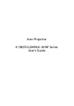
Data Output after Measurements When Handshaking Is Enabled
●
Data Output after Measurements When Handshaking Is Disabled
During execution of continuous measurements, the BUSY signal remains ON. The Vision Sensor will acknowledge
the EXE signal only after the End Continuous Measurements command is executed.
Note
Second data output
*2
First data output
(1)
(2)
(4)
(5)
(3)
Data Output
Request Bit (DSA)
signal
Output data 1
to 64(DATA1 to
DATA64)
Data Output
Completed (GATE)
signal
*1
*1
ON
OFF
ON
OFF
ON
OFF
Output Area
(1)
After measurements are completed, the Data Output Request Bit (DSA) signal is turned ON by the PLC and a request is
made to the Vision Sensor to output the data.
(2)
The Vision Sensor outputs the data. After the data is output, the Data Output Completed (GATE) signal turns ON.
(3)
The master confirms that the Data Output Completed (GATE) signal has turned ON, loads the data, and turns OFF the
Data Output Request Bit (DSA) signal.
(4)
When the Vision Sensor detects that the Data Output Request (DSA) signal is OFF, it automatically turns OFF the Data
Output Completed (GATE) signal.
(5)
The Data Output Request Bit (DSA) signal is turned ON from the PLC and a request is made to output the data.
*1 I
f the data output request signal is not manipulated within the control timeout time (100 to 120,000 ms) in the
EtherNet/IP settings, and data output error will occur and the ERR signal will turn ON. When the ERCLR signal is turned
ON, the ERR signal will turn OFF. However, if a timeout occurs again, the ERR signal will turn ON again. Therefore,
correctly request data output (DSA control) or execute a Clear Data Output Buffer command.
*2 Indicates that the data to output is separated and output more than once.
Command
Area
Response
Area
Here, the Vision Sensor ends
measurements and can output data.
Data Output
Completed
(GATE) signal
Output data 1 to 64
(DATA1 to DATA64)
(2)
(1)
The data is output according to the set
output cycle (1) and output time (2).
After data output is completed, the
GATE signal turns ON and the output
data is maintained for the data output
hold time.
Output Area
Response
Area
ON
OFF
ON
OFF
Here, the Vision Sensor ends measurements and can output data.
Summary of Contents for FQ2-S4
Page 1: ...User s Manual Smart Camera FQ2 S4 Cat No Z330 E1 01 ...
Page 58: ...Setting Up Ethernet 56 FQ2 S4 User s Manual MEMO ...
Page 214: ...Calculations and Judgements Using Inspection Item Data 212 FQ2 S4 User s Manual MEMO ...
Page 234: ...Adjusting Judgement Parameters during Operation 232 FQ2 S4 User s Manual MEMO ...
Page 458: ...Basic Troubleshooting 456 FQ2 S4 User s Manual MEMO ...
Page 591: ...Index FQ2 S4 User s Manual 589 Index 12 ...
Page 593: ......