Controlling Operation and Outputting Data with the Sensor's Standard Parallel Connection
284
FQ2-S4 User’s Manual
Wiring
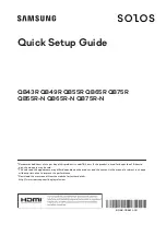
Timing Chart
1. Turn ON IN5 while IN0 to IN4 are OFF. If status is held while the BUSY signal is OFF, continuous
measurements will begin and the BUSY signal will remain ON while continuous measurements are being
performed.
2. Continuous measurements end when IN5 is turned OFF.
Settings
[In/Out]
−
[I/O setting]
−
[I/O terminals]
−
[Input]
−
[Input mode]
Press [Expanded mode].
Color
Signal
State
Description
The signals shown at the left
are used.
Refer to the following informa-
tion for signal wiring.
Wiring: p. 42
Gray
IN0
OFF
Command parameters for continu-
ous measurements
Green
IN1
OFF
Red
IN2
OFF
White
IN3
OFF
Purple
IN4
OFF
Yellow
IN5
ON
Command input for continuous
measurements
Black
OUT0 (OR)
--
Overall judgement (default assign-
ment)
Orange
OUT1 (BUSY)
--
Processing in progress (default
assignment)
OFF
ON
OFF
ON
OFF
ON
OR signal
Turned ON when overall judgement is NG.
(OR output: ON for NG)
ON while measurements are
being processed (depends on
BUSY output conditions)
BUSY signal
Start continuous measurements
End continuous measurements
IN5 signal
IN0 to IN4 signals
are OFF
Allow 5 ms min. and then turn ON IN5.
Summary of Contents for FQ2-S4
Page 1: ...User s Manual Smart Camera FQ2 S4 Cat No Z330 E1 01 ...
Page 58: ...Setting Up Ethernet 56 FQ2 S4 User s Manual MEMO ...
Page 214: ...Calculations and Judgements Using Inspection Item Data 212 FQ2 S4 User s Manual MEMO ...
Page 234: ...Adjusting Judgement Parameters during Operation 232 FQ2 S4 User s Manual MEMO ...
Page 458: ...Basic Troubleshooting 456 FQ2 S4 User s Manual MEMO ...
Page 591: ...Index FQ2 S4 User s Manual 589 Index 12 ...
Page 593: ......