CHAPTER 11 WATCHDOG TIMER FUNCTIONS
User’s Manual U16896EJ2V0UD
354
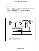
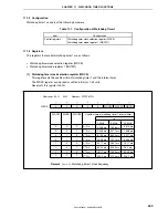
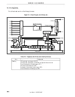
11.2.2 Configuration
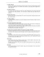
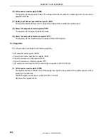
Watchdog timer 2 consists of the following hardware.
Table 11-4. Configuration of Watchdog Timer 2
Item Configuration
Control registers
Watchdog timer mode register 2 (WDTM2)
Watchdog timer enable register (WDTE)
11.2.3 Registers
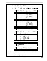
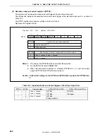
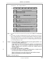
(1) Watchdog timer mode register 2 (WDTM2)
This register sets the overflow time and operation clock of watchdog timer 2.
The WDTM2 register can be read or written in 8-bit units. This register can be read any number of times, but it
can be written only once following reset release.
Reset sets this register to 67H.
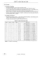
Caution Accessing the WDTM2 register is prohibited in the following statuses. For details, refer to
3.4.8 (1) (b) Access to special on-chip peripheral I/O register.
•
When the CPU operates on the subclock and the main clock oscillation is stopped
•
When the CPU operates on the internal oscillation clock
0
WDTM2
WDM21
WDM20 WDCS24 WDCS23 WDCS22 WDCS21 WDCS20
After reset: 67H R/W Address: FFFFF6D0H
Stops operation
Non-maskable interrupt request mode (generation of INTWDT2)
Reset mode (generation of WDTRES2)
WDM21
0
0
1
WDM20
0
1
–
Selection of operation mode of watchdog timer 2
Cautions 1. To stop the operation of watchdog timer 2, write “1FH” to the WDTM2 register.
2. For details about bits WDCS0 to WDCS4, refer to Table 11-5 Watchdog Timer 2 Clock
Selection.
3. If the WDTM2 register is written twice after a reset, an overflow signal is forcibly output.
4. To intentionally generate an overflow signal, write data to the WDTM2 register only twice,
or write a value other than “ACH” to the WDTE register only once.
<R>
<R>

