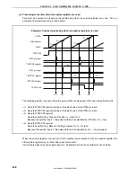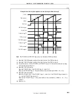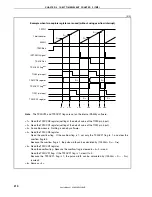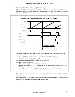
CHAPTER 6 16-BIT TIMER/EVENT COUNTER P (TMP)
User’s Manual U16896EJ2V0UD
216
Figure 6-36. Register Setting in Pulse Width Measurement Mode (1/2)
(a) TMP0 control register 0 (TP0CTL0)
0/1
0
0
0
0
TP0CTL0
Select count clock
Note
0: Stop counting
1: Enable counting
0/1
0/1
0/1
TP0CKS2 TP0CKS1 TP0CKS0
TP0CE
Note
Setting is invalid when the TP0EEE bit = 1.
(b) TMP0 control register 1 (TP0CTL1)
0
0
0/1
0
0
TP0CTL1
1
1
0
TP0MD2 TP0MD1 TP0MD0
TP0EEE
TP0EST
1, 1, 0:
Pulse width measurement mode
0: Operate with count
clock selected by
TP0CKS0 to TP0CKS2 bits
1: Count external event
count input signal
(c) TMP0 I/O control register 1 (TP0IOC1)
0
0
0
0
0/1
TP0IOC1
Select valid edge
of TIP00 pin input
Select valid edge
of TIP01 pin input
0/1
0/1
0/1
TP0IS2
TP0IS1
TP0IS0
TP0IS3
(d) TMP0 I/O control register 2 (TP0IOC2)
0
0
0
0
0/1
TP0IOC2
Select valid edge of
external event count input
0/1
0
0
TP0EES0 TP0ETS1 TP0ETS0
TP0EES1

