CHAPTER 7 16-BIT TIMER/EVENT COUNTER 0
User’s Manual U16896EJ2V0UD
229
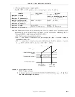
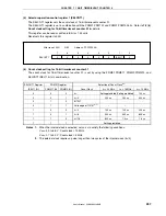
(c) Setting range when used as compare register
When the CR010 or CR011 register is used as a compare register, set it as shown below.
Operation
CR010 Register
CR011 Register
•
Operation as interval timer
•
Operation as square-wave output
•
Operation as external event counter
0000H < N
≤
FFFFH
0000H
Note
≤
M
≤
FFFFH
Normally, this setting is not used. Mask the
match interrupt signal (INTTM011).
•
Operation in the clear & start mode
entered by TI010 pin valid edge input
•
Operation as free-running timer
0000H
Note
≤
N
≤
FFFFH
0000H
Note
≤
M
≤
FFFFH
•
Operation as PPG output
M < N
≤
FFFFH
0000H
Note
≤
M
≤
N
•
Operation as one-shot pulse output
0000H
Note
≤
N
≤
FFFFH (N
≠
M)
0000H
Note
≤
M
≤
FFFFH (M
≠
N)
Note
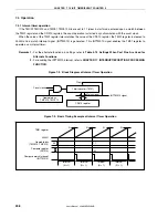
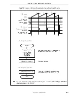
When 0000H is set, a match interrupt immediately after the timer operation does not occur and timer output
is not changed, and the first match timing is as follows. A match interrupt occurs at the timing when the
timer counter (TM01 register) is changed from 0000H to 0001H.
•
When the timer counter is cleared due to overflow
•
When the timer counter is cleared due to TI010 pin valid edge (when clear & start mode is entered by
TI010 pin valid edge input)
•
When the timer counter is cleared due to compare match (when clear & start mode is entered by match
between TM01 and CR010 (CR010 = other than 0000H, CR011 = 0000H))
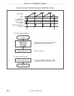
Operation enabled
(other than 00)
TM01 register
Timer counter clear
Interrupt signal
is not generated
Interrupt signal
is generated
Timer operation enable bit
Interrupt request signal
Compare register set value
(0000H)
Operation
disabled (00)
Remarks 1.
N: CR010 register set value
M: CR011 register set value
2.
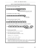
For details of operation enable bits (TMC01.TMC013, TMC01.TMC012 bits), refer to
7.3 (1) 16-bit
timer mode control register 01 (TMC01)
.


