
CHAPTER 7 16-BIT TIMER/EVENT COUNTER 0
User’s Manual U16896EJ2V0UD
266
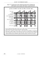
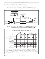
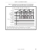
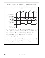
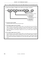
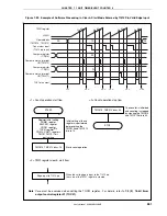
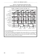
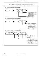
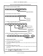
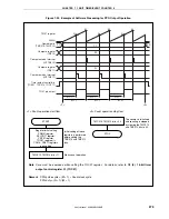
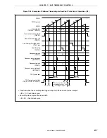
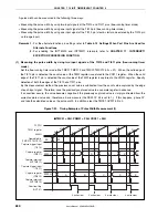
Figure 7-28. Timing Example of Free-Running Timer Mode
(CR010 Register: Capture Register, CR011 Register: Capture Register) (1/2)
(a) TOC01 = 13H, PRM01 = 0 to 50H, CRC01 = 05H, TMC01 = 04H
01
M
A
B
C
D
E
N
S
P
Q
00
0000H
A
B
C
D
E
0000H
M
N
S
P
Q
FFFFH
TM01 register
0000H
Operable bits
(TMC013, TMC012)
Capture trigger input
(TI010)
Capture register
(CR011)
Capture interrupt
(INTTM011)
Capture trigger input
(TI011)
Capture register
(CR010)
Capture interrupt
(INTTM010)
Overflow flag
(OVF01)
0 write clear
0 write clear
0 write clear
0 write clear
This is an application example where the count values that have been captured at the valid edges of separate
capture trigger signals are stored in separate capture registers in the free-running timer mode.
The count value is captured to the CR011 register when the valid edge of the TI010 pin input is detected and to
the CR010 register when the valid edge of the TI011 pin input is detected.


