


CHAPTER 7 16-BIT TIMER/EVENT COUNTER 0
User’s Manual U16896EJ2V0UD
285
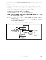
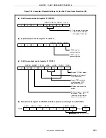
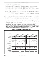
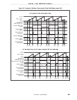
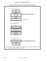
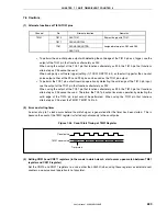
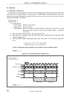
Figure 7-43. Example of Software Processing for Pulse Width Measurement (1/2)
(a) Example of free-running timer mode
FFFFH
TM01 register
0000H
Operable bits
(TMC013, TMC012)
Capture trigger input
(TI010)
Capture register
(CR011)
Capture interrupt
(INTTM011)
Capture trigger input
(TI011)
Capture register
(CR010)
Capture interrupt
(INTTM010)
01
D
00
D
00
D
01
D
01
D
02
D
02
D
03
D
03
D
04
D
04
D
10
D
10
D
11
D
11
D
12
D
12
D
13
D
13
00
00
0000H
0000H
<1> <2> <2>
<2>
<2>
<2> <2>
<2>
<2>
<2><3>
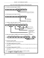
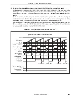
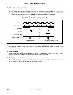
(b) Example of clear & start mode entered by TI010 pin valid edge
FFFFH
TM01 register
0000H
Operable bits
(TMC013, TMC012)
Capture & count clear input
(TI010)
Capture register
(CR010)
Capture interrupt
(INTTM010)
Capture register
(CR011)
Capture interrupt
(INTTM011)
10
D
0
L
D
0
D
1
D
1
D
2
D
2
D
3
D
3
D
4
D
4
D
5
D
5
D
6
D
6
D
7
D
7
D
8
D
8
00
00
0000H
0000H
<1>
<2> <2>
<2>
<2>
<2>
<2> <2>
<2> <3>
<2>


