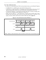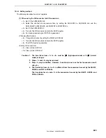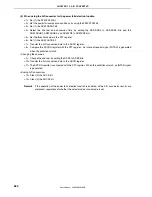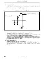
CHAPTER 13 A/D CONVERTER
User’s Manual U16896EJ2V0UD
374
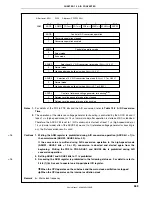
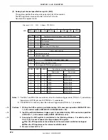
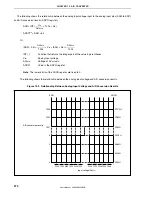
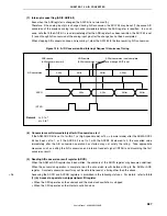
The following shows the relationship between the analog input voltage input to the analog input pins (ANI0 to ANI7)
and A/D conversion results (ADCR register).
SAR = INT (
×
1024 + 0.5)
ADCR
Note
= SAR
×
64
Or,
(SAR
−
0.5)
×
≤
V
IN
< (SAR + 0.5)
×
INT ( ):
Function that returns the integer part of the value in parentheses
V
IN
:
Analog input voltage
AV
REF0
:
Voltage of AV
REF0
pin
ADCR:
Value in the ADCR register
Note
The lower 6 bits of the ADCR register are fixed to 0.
The following shows the relationship between the analog input voltage and A/D conversion results.
Figure 13-3. Relationship Between Analog Input Voltage and A/D Conversion Results
1023
1022
1021
FFC0H
FF80H
FF40H
3
2
1
0
00C0H
0080H
0040H
0000H
Input voltage/AV
REF0
1
2048
1
1024
3
2048
2
1024
5
2048
3
1024
2043
2048
1022
1024
2045
2048
1023
1024
2047
2048
1
A/D conversion results
SAR
ADCR
V
IN
AV
REF0
AV
REF0
1024
AV
REF0
1024

