


CHAPTER 20 RESET FUNCTION
User’s Manual U16896EJ2V0UD
597
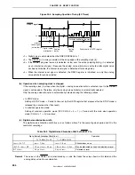
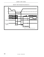
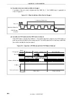
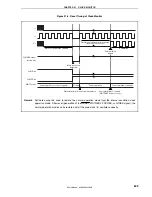
20.4.4 Power-on-clear reset operation
The supply voltage (V
DD
) and detection voltage (V
POC
) are compared. When V
DD
< V
POC
, the system is reset and
each hardware unit is initialized to a specific status.
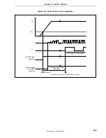
The detection voltage (V
POC
) is 2.6 V
±
0.1 V.
While V
DD
< V
POC
, the system is reset. Reset is released when V
DD
≥
V
POC
. After release of the reset status, the
oscillation stabilization time of the main clock oscillator is secured, and then the CPU starts program execution.
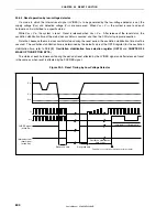
Note that, because the main clock oscillator stops during the reset period, the oscillation stabilization time must be
secured. The oscillation stabilization time is determined by the default value of the OSTS register (for the oscillation
stabilization time, refer to
19.2 (3) Oscillation stabilization time selection register (OSTS)
and
CHAPTER 25
MASK OPTION/OPTION BYTE
).
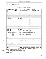
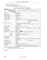
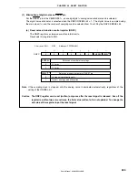
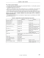
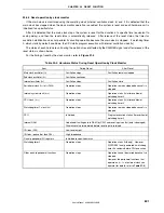
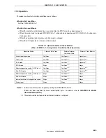
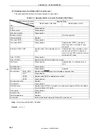
The following table shows the status of each hardware unit during the period of reset effected by the POCRES
signal and after release of reset.
Table 20-4. Hardware Status During Reset Operation by Power-on-Clear
Item
During Reset
After Reset
Main clock oscillator (f
X
)
Oscillation stops
Oscillation starts
Subclock oscillator (f
XT
) Oscillation
continues
Internal oscillator (f
R
)
Oscillation stops
Oscillation starts
Peripheral clock (f
XX
to f
XX
/1024) Operation
stops
Operation starts after securing oscillation
stabilization time
Internal system clock (f
CLK
) Operation
stops
Operation starts after securing oscillation
stabilization time (initialized to f
XX
/8)
CPU clock (f
CPU
) Operation
stops Operation starts after securing oscillation
stabilization time (initialized to f
XX
/8)
Watchdog timer 1 clock (f
XW
) Operation
stops
Operation starts
CPU Initialized
Program execution starts after securing
oscillation stabilization time
Internal RAM
Undefined if power-on reset or writing data to RAM (by CPU) and reset input conflict
(data is damaged).
Otherwise value immediately before reset input is retained.
I/O lines (P00)
Low-level output
I/O lines (ports other than P00)
High impedance
On-chip peripheral I/O registers
Initialized to specified status
Watchdog timer 2
Operation stops Operation
starts
(f
R
/8)
Other on-chip peripheral functions Operation
stops
Operation can be started after securing
oscillation stabilization time


