User’s Manual U16896EJ2V0UD
365
CHAPTER 13 A/D CONVERTER
13.1 Overview
The A/D converter converts analog input signals into digital values and has an 8-channel (ANI0 to ANI7)
configuration.
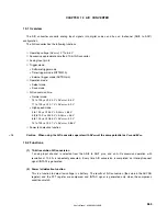
The A/D converter has the following functions.
○
Operating voltage (AV
REF0
): 2.7 to 5.5 V
○
Successive approximation method 10-bit A/D converter
○
Analog input pin: 8
○
Trigger mode:
•
Software trigger mode
•
Timer trigger mode (INTTM010)
•
External trigger mode (ADTRG pin)
○
Operation mode
•
Select mode
•
Scan mode
○
A/D conversion time:
•
Normal mode:
14 to 100
μ
s @ 4.0 V
≤
AV
REF0
≤
5.5 V
17 to 100
μ
s @ 2.7 V
≤
AV
REF0
< 4.0 V
•
High-speed mode:
3 to 100
μ
s @ 4.5 V
≤
AV
REF0
≤
5.5 V
4.8 to 100
μ
s @ 4.0 V
≤
AV
REF0
< 4.5 V
6 to 100
μ
s @ 2.85 V
≤
AV
REF0
< 4.0 V
14 to 100
μ
s @ 2.7 V
≤
AV
REF0
< 2.85 V
○
Power fail detection function
Caution When using the A/D converter, operate with AV
REF0
at the same potential as V
DD
and EV
DD
.
13.2 Functions
(1) 10-bit resolution A/D conversion
1 analog input channel is selected from the ANI0 to ANI7 pins, and an A/D conversion operation with
resolution of 10 bits is repeatedly executed. Every time A/D conversion is completed, an interrupt request
signal (INTAD) is generated.
(2) Power fail detection function
This is a function to detect low voltage in a battery. The results of A/D conversion (the value in the ADCRH
register) and the PFT register are compared, and INTAD signal is generated only when the comparison
conditions match.
<R>

