CHAPTER 7 16-BIT TIMER/EVENT COUNTER 0
User’s Manual U16896EJ2V0UD
282
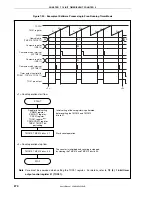
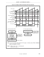
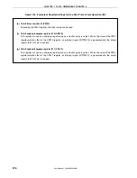
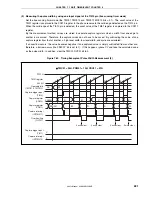
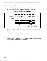
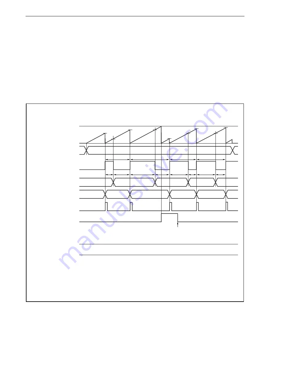
(3) Measuring the pulse width by using one input signal of the TI010 pin (clear & start mode entered by the
TI010 pin valid edge input)
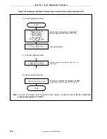
Set the clear & start mode entered by the TI010 pin valid edge (the TMC01.TMC013 and TMC01.TMC012 bits =
10). The count value of the TM01 register is captured to the CR010 register in the phase reverse to the valid
edge of the TI010 pin, and the count value of the TM01 register is captured to the CR011 register and the TM01
register is cleared (0000H) when the valid edge of the TI010 pin is detected. Therefore, a cycle is stored in the
CR011 register if the TM01 register does not overflow.
If an overflow occurs, take the value that results from adding 10000H to the value stored in the CR011 register as
a cycle. Clear the TMC01.OVF01 bit to 0.
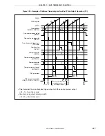
Figure 7-41. Timing Example of Pulse Width Measurement (3)
•
TMC01 = 08H, PRM01 = 10H, CRC01 = 07H
FFFFH
TM01 register
0000H
Operable bits
(TMC013, TMC012)
Capture & count clear input
(TI010)
Capture register
(CR010)
Capture register
(CR011)
Capture interrupt
(INTTM011)
Overflow flag
(OVF01)
Capture trigger input
(TI011)
Capture interrupt
(INTTM010)
10
<1>
<2>
<3>
<3>
<3>
<3>
<2>
<2>
<2>
<1>
<1>
<1>
M
A
B
C
D
N
S
P
Q
00
00
0 write clear
0000H
L
L
A
B
C
D
0000H
M
N
S
P
Q
<1> Pulse cycle =
(10000H
×
Number of times OVF01 bit is set to 1 + Captured value of the
CR011 register)
×
Count clock cycle
<2> High-level pulse width = (10000H
×
Number of times OVF01 bit is set to 1 + Captured value of the
CR010 register)
×
Count clock cycle
<3> Low-level pulse width = (Pulse cycle
−
High-level pulse width)

