CHAPTER 6 16-BIT TIMER/EVENT COUNTER P (TMP)
User’s Manual U16896EJ2V0UD
183
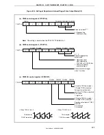
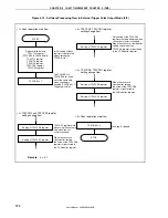
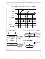
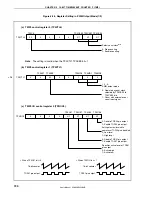
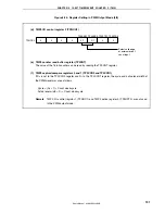
Figure 6-22. Setting of Registers in One-Shot Pulse Output Mode (1/2)
(a) TMP0 control register 0 (TP0CTL0)
0/1
0
0
0
0
TP0CTL0
Select count clock
Note
0: Stop counting
1: Enable counting
0/1
0/1
0/1
TP0CKS2 TP0CKS1 TP0CKS0
TP0CE
Note
The setting is invalid when the TP0CTL1.TP0EEE bit = 1.
(b) TMP0 control register 1 (TP0CTL1)
0
0/1
0/1
0
0
TP0CTL1
0: Operate on count clock
selected by TP0CKS0 to
TP0CKS2 bits
1: Count external event
input signal
Generate software trigger
when 1 is written
0
1
1
TP0MD2 TP0MD1 TP0MD0
TP0EEE
TP0EST
0, 1, 1:
One-shot pulse output mode
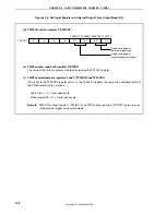
(c) TMP0 I/O control register 0 (TP0IOC0)
0
0
0
0
0/1
TP0IOC0
0: Disable TOP00 pin output
1: Enable TOP00 pin output
Setting of output level while
operation of TOP00 pin is disabled
0: Low level
1: High level
0: Disable TOP01 pin output
1: Enable TOP01 pin output
Specifies active level of
TOP01 pin output
0: Active-high
1: Active-low
0/1
0/1
0/1
TP0OE1
TP0OL0
TP0OE0
TP0OL1
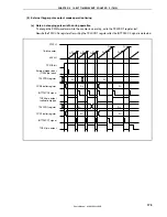
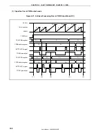
TOP01 pin output
16-bit counter
•
When TP0OL1 bit = 0
TOP01 pin output
16-bit counter
•
When TP0OL1 bit = 1

