


CHAPTER 14 ASYNCHRONOUS SERIAL INTERFACE (UART)
User’s Manual U16896EJ2V0UD
423
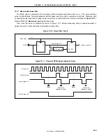
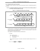
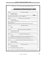
(3) SBF reception
The reception enabled status is achieved by setting the ASIM0.UARTE0 bit to 1 and then setting the
ASIM0.RXE0 bit to 1.
The SBF reception wait status is set by setting the SBF reception trigger (ASICL0.SBRT0 bit) to 1.
In the SBF reception wait status, similarly to the UART reception wait status, the RXD0 pin is monitored and
start bit detection is performed.
Following detection of the start bit, reception is started and the internal counter counts up according to the set
baud rate.
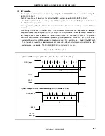
When a stop bit is received, if the SBF width is 11 or more bits, normal processing is judged and a reception
completion interrupt request signal (INTSR0) is output. The ASICL0.SBRF0 bit is automatically cleared and
SBF reception ends. Error detection for the ASIS0.PE0, ASIS0.FE0, and ASIS0.OVE0 bits is suppressed
and UART communication error detection processing is not performed. Moreover, data transfer of the
reception shift register and RXB0 register is not performed and FFH, the initial value, is held. If the SBF width
is 10 or fewer bits, reception is terminated as error processing without outputting an interrupt, and the SBF
reception mode is returned to. The ASICL0.SBRF0 bit is not cleared at this time.
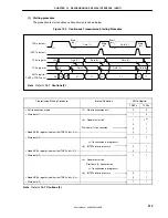
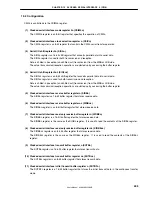
Figure 14-15. SBF Reception
(a) Normal SBF reception (detection of stop bit in more than 10.5 bits)
SBRF0
1
2
3
4
5
6
11.5
7
8
9
10
11
INTST0
interrupt
RXD0 (input)
(b) SBF reception error (detection of stop bit in 10.5 or fewer bits)
SBRF0
RXD0 (input)
1
2
3
4
5
6
10.5
7
8
9
10
INTST0
interrupt


