


CHAPTER 17 INTERRUPT/EXCEPTION PROCESSING FUNCTION
User’s Manual U16896EJ2V0UD
552
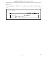
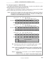
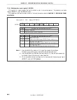
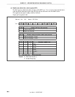
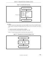
17.3.8 Watchdog timer mode register 1 (WDTM1)
This register is a special register that can be written to only in a special sequence. To generate a maskable
interrupt (INTWDT1), clear the WDTM14 bit to 0.
This register can be read or written in 8-bit or 1-bit units (for details, refer to
CHAPTER 11 WATCHDOG TIMER
FUNCTIONS
).
RUN1
Stop count operation
Clear counter and start count operation
RUN1
0
1
Watchdog timer operation mode selection
Note 1
WDTM1
0
0
WDTM14 WDTM13
0
0
0
After reset: 00H R/W Address: FFFFF6C2H
Interval timer mode
(Generate maskable interrupt INTWDTM1 when overflow occurs)
Watchdog timer mode 1
Note 3
(Generate non-maskable interrupt INTWDT1 when overflow occurs)
Watchdog timer mode 2
(Start WDTRES2 reset operation when overflow occurs)
WDTM14
0
0
1
1
WDTM13
0
1
0
1
Watchdog timer operation mode selection
Note 2
< >
Notes 1.
Once the RUN1 bit has been set (1), it cannot be cleared (0) by software.
Therefore, once counting starts, it cannot be stopped except by reset.
2.
Once the WDTM14 and WDTM13 bits have been set (1), they cannot be cleared (0)
by software. Reset is the only way to clear these bits.
3.
For non-maskable interrupt servicing due to a non-maskable interrupt request signal
(INTWDT1), refer to
17.10 Cautions
.


