


CHAPTER 1 INTRODUCTION
User’s Manual U16896EJ2V0UD
31
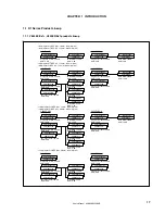
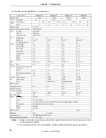
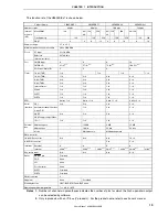
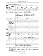
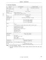
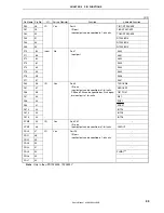
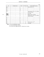
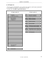
1.7 Overview of Functions
Part Number
μ
PD703302, 703302Y
μ
PD70F3302, 70F3302Y
ROM
128 KB
128 KB (single-power flash memory)
Internal
memory
High-speed RAM
4 KB
Memory space
64 MB
General-purpose registers
32 bits
×
32 registers
Ceramic/crystal/external clock
When PLL not used (2 to 10 MHz: 2.7 to 5.5 V)
Main clock
(oscillation frequency)
When PLL used (2 to 5 MHz: 4.5 to 5.5 V, 2 to 2.5 MHz: 2.7 to 5.5 V)
Subclock
(oscillation frequency)
Crystal/external clock
(32.768 kHz)
Minimum instruction
execution time
50 ns (When main clock operated at (f
XX
) = 20 MHz)
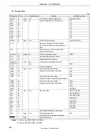
DSP function
32
×
32 = 64: 200 to 250 ns (at 20 MHz)
32
×
32 + 32 = 32: 300 ns (at 20 MHz)
16
×
16 = 32: 50 to 100 ns (at 20 MHz)
16
×
16 + 32 = 32: 150 ns (at 20 MHz)
I/O ports
51
•
Input: 8
•
I/O: 43 (among these, N-ch open-drain output selectable: 4, fixed to N-ch open-drain output: 2)
Timer
16-bit timer/event counter P: 1 channel
16-bit timer/event counter 0: 1 channel
8-bit timer/event counter 5: 2 channels
(16-bit timer/event counter: Usable as 1 channel)
8-bit timer H: 2 channels
Watchdog timer: 2 channels
Watch timer: 1 channel
8-bit interval timer: 1 channel
Real-time output port
4 bits
×
1, 2 bits
×
1, or 6 bits
×
1
A/D converter
10-bit resolution
×
8 channels
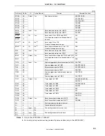
Serial interface
CSI: 2 channels
UART (supporting LIN): 1 channel
UART: 1 channel
I
2
C bus: 1 channel
Note 1
Dedicated baud rate generator: 2 channels
Interrupt sources
External: 10 (10)
Note 2
, internal: 27/26
Note 1
Power save function
STOP/IDLE/HALT/sub-IDLE mode
Operating supply voltage
4.5 to 5.5 V (at 20 MHz)/2.7 to 5.5 V (at 10 MHz)
Package
64-pin plastic TQFP (12
×
12 mm)
64-pin plastic LQFP (fine pitch) (10
×
10 mm)
Notes 1.
Only in the
μ
PD703302Y, 70F3302Y
2.
The figure in parentheses indicates the number of external interrupts for which STOP mode can be
released.
<R>
<R>


