CHAPTER 10 INTERVAL TIMER, WATCH TIMER
User’s Manual U16896EJ2V0UD
342
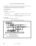
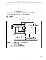
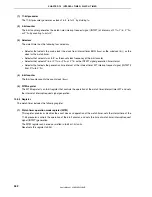
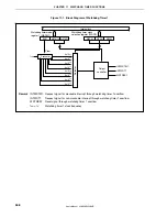
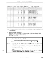
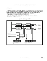
(1) 11-bit
prescaler
The 11-bit prescaler generates a clock of f
W
/2
4
to f
W
/2
11
by dividing f
W
.
(2) 5-bit
counter
The 5-bit counter generates the watch timer interrupt request signal (INTWT) at intervals of 2
4
/f
W
, 2
5
/f
W
, 2
13
/f
W
,
or 2
14
/f
W
by counting f
W
or f
W
/2
9
.
(3) Selectors
The watch timer has the following four selectors.
•
Selector that selects the main clock (the clock from interval timer BRG (f
BRG
) or the subclock (f
XT
)) as the
clock for the watch timer.
•
Selector that selects f
W
or f
W
/2
9
as the count clock frequency of the 5-bit counter
•
Selector that selects 2
4
/f
W
or 2
13
/f
W
, or 2
5
/f
W
or 2
14
/f
W
as the INTWT signal generation time interval.
•
Selector that selects the generation time interval of the interval timer WT interrupt request signal (INTWTI)
from 2
4
/f
W
to 2
11
/f
W
.
(4) 8-bit
counter
The 8-bit counter counts the count clock (f
BGCS
).
(5) WTM
register
The WTM register is an 8-bit register that controls the operation of the watch timer/interval timer WT and sets
the interval of interrupt request signal generation.
10.2.3 Register
The watch timer includes the following register.
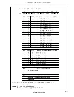
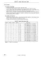
(1) Watch timer operation mode register (WTM)
This register enables or disables the count clock and operation of the watch timer, sets the interval time of the
11-bit prescaler, controls the operation of the 5-bit counter, and sets the time of watch timer interrupt request
signal (INTWT) generation.
The WTM register can be read or written in 8-bit or 1-bit units.
Reset sets this register to 00H.

