


CHAPTER 7 16-BIT TIMER/EVENT COUNTER 0
User’s Manual U16896EJ2V0UD
284
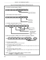
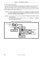
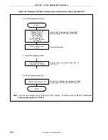
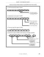
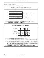
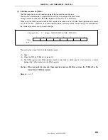
Figure 7-42. Example of Register Settings for Pulse Width Measurement Operation (2/2)
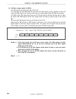
(e) 16-bit timer counter 01 (TM01)
By reading the TM01 register, the count value can be read.
(f) 16-bit capture/compare register 010 (CR010)
This register is used as a capture register. Either the TI010 or TI011 pin is selected as a capture trigger.
When a specified edge of the capture trigger is detected, the count value of the TM01 register is stored in
the CR010 register.
(g) 16-bit capture/compare register 011 (CR011)
This register is used as a capture register. The signal input to the TI010 pin is used as a capture trigger.
When the capture trigger is detected, the count value of the TM01 register is stored in the CR011 register.


