


CHAPTER 8 8-BIT TIMER/EVENT COUNTER 5
User’s Manual U16896EJ2V0UD
297
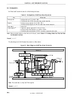
8.3 Registers
The following two registers are used to control 8-bit timer/event counter 5n.
•
Timer clock selection register 5n (TCL5n)
•
8-bit timer mode control register 5n (TMC5n)
Remark
To use the functions of the TI5n and TO5n pins, refer to
Table 4-12 Settings When Port Pins Are
Used for Alternate Functions
.
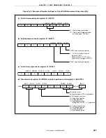
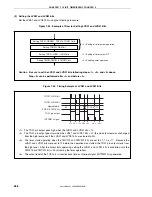
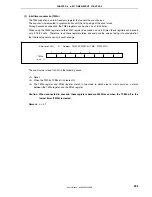
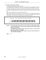
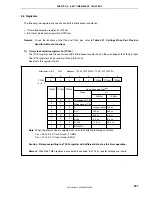
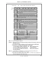
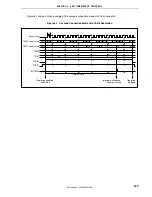
(1) Timer clock selection register 5n (TCL5n)
The TCL5n register sets the count clock of 8-bit timer/event counter 5n and the valid edge of the TI5n pin input.
The TCL5n register can be read or written in 8-bit units.
Reset sets this register to 00H.
Falling edge of TI5n
Rising edge of TI5n
f
XX
f
XX
/2
f
XX
/4
f
XX
/64
f
XX
/256
INTTM010
Count clock selection
Note
TCL5n2
0
0
0
0
1
1
1
1
TCL5n1
0
0
1
1
0
0
1
1
TCL5n0
0
1
0
1
0
1
0
1
20 MHz
10 MHz
–
–
Setting prohibited
100 ns
200 ns
3.2 s
12.8 s
–
–
–
100 ns
200 ns
0.4 s
6.4 s
25.6 s
–
Clock
f
XX
0
TCL5n
(n = 0, 1)
0
0
0
0
TCL5n2
TCL5n1
TCL5n0
After reset: 00H R/W Address: TCL50 FFFFF5C4H, TCL51 FFFFF5C5H
7
6
5
4
3
2
1
0
μ
μ
μ
μ
μ
Note
When the internal clock is selected, set so as to satisfy the following conditions.
V
DD
= 4.0 to 5.5 V: Count clock
≤
10 MHz
V
DD
= 2.7 to 4.0 V: Count clock
≤
5 MHz
Caution Before overwriting the TCL5n register with different data, stop the timer operation.
Remark
When the TM5n register is connected in cascade, the TCL51 register settings are invalid.


