CHAPTER 19 STANDBY FUNCTION
User’s Manual U16896EJ2V0UD
574
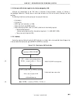
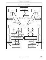
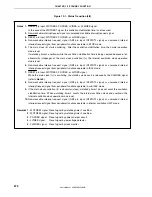
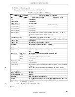
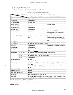
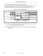
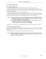
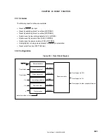
Figure 19-1. Status Transition (2/2)
Notes 1.
RESET pin input, WDTRES2, POCRES, LVIRES, or CLMRES signal.
In the case of the WDTRES1 signal, the oscillation stabilization time is not secured.
2.
Non-maskable interrupt request signal or unmasked maskable interrupt request signal.
3.
RESET pin input, WDTRES2, POCRES, or LVIRES signal.
4.
Non-maskable interrupt request signal (NMI pin input, INTWDT2 signal) or unmasked internal
interrupt request signal from peripheral functions operable in STOP mode.
5.
The main clock (f
X
) starts oscillating. After the oscillation stabilization time, the normal operation
mode is set.
If watchdog timer 2 overflows while the oscillation stabilization time is being secured because of an
abnormality (stoppage) of the main clock oscillation (f
X
), the internal oscillation clock operation
mode is set.
6.
Non-maskable interrupt request signal (NMI pin input, INTWDT2 signal) or unmasked internal
interrupt request signal from peripheral functions operable in IDLE mode.
7.
RESET pin input, WDTRES2, POCRES, or LVIRES signal.
While the main clock (f
X
) is oscillating, the standby mode can be released by the CLMRES signal
(refer to
Note 9
).
8.
Non-maskable interrupt request signal (NMI pin input, INTWDT2 signal) or unmasked internal
interrupt request signal from peripheral functions operable in sub-IDLE mode.
9.
If the main clock oscillation (f
X
) is abnormal (stops), watchdog timer 1 does not count the oscillation
stabilization time. When watchdog timer 2 counts the internal oscillation clock and overflows, the
internal oscillation clock operation mode is set.
10.
Non-maskable interrupt request signal (NMI pin input, INTWDT2 signal) or unmasked internal
interrupt request signal from peripheral functions operable in internal oscillation HALT mode.
Remarks 1.
WDTRES1 signal: Reset signal by watchdog timer 1 overflow
2.
WDTRES2 signal: Reset signal by watchdog timer 2 overflow
3.
POCRES signal: Reset signal by power-on-clear circuit
4.
LVIRES signal:
Reset signal by low-voltage detector
5.
CLMRES signal: Reset signal by clock monitor


