


CHAPTER 7 16-BIT TIMER/EVENT COUNTER 0
User’s Manual U16896EJ2V0UD
239
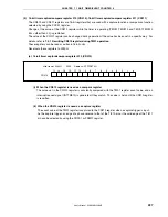
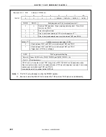
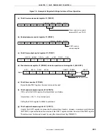
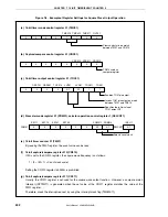
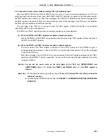
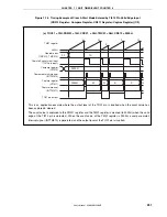
Figure 7-4. Example of Register Settings for Interval Timer Operation
(a) 16-bit timer mode control register 01 (TMC01)
0
0
0
0
1
1
0
0
TMC013 TMC012 TMC011
OVF01
Clears and starts on match
between TM01 and CR010.
(b) Capture/compare control register 01 (CRC01)
0
0
0
0
0
0
0
0
CRC012 CRC011 CRC010
CR010 used as
compare register
(c) 16-bit timer output control register 01 (TOC01)
0
0
0
0
0
LVR01
LVS01
TOC014
OSPE01
OSPT01
TOC011
TOE01
0
0
0
(d) Prescaler mode register 01 (PRM01), selector operation control register 1 (SELCNT1)
0
PRM01
0
0
0
0
PRM011
PRM010
SELCNT1
ES111
ES110
ES101
ES100
Selects count clock.
0
0/1
0/1
ISEL11
0/1
(e) 16-bit timer counter 01 (TM01)
By reading the TM01 register, the count value can be read.
(f) 16-bit capture/compare register 010 (CR010)
If M is set to the CR010 register, the interval time is as follows.
Interval time = (M + 1)
×
Count clock cycle
Setting the CR010 register to 0000H is prohibited.
(g) 16-bit capture/compare register 011 (CR011)
Usually, the CR011 register is not used for the interval timer function. However, a compare match interrupt
(INTTM011) is generated when the set value of the CR011 register matches the value of the TM01 register.
Therefore, mask the interrupt request by using the interrupt mask flag (TM0MK11).


