CHAPTER 6 16-BIT TIMER/EVENT COUNTER P (TMP)
User’s Manual U16896EJ2V0UD
222
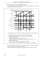
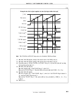
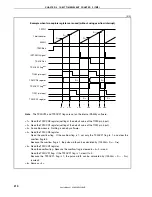
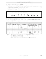
<Setting procedure>
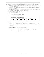
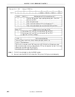
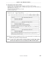
<1> Select the number of times of sampling and the sampling clock by using the PaNFC register.
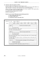
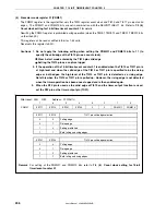
<2> Select the alternate function (of the TIP0a pin) by using the PMC3, PFC3, and PFCE3 registers.
<3> Set the operating mode of TMP0 (such as the capture mode or the valid edge of the capture trigger).
<4> Enable the TMP0 count operation.
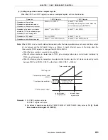
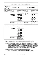
<Noise elimination width>
The digital noise elimination width (t
WTIP0a
) is as follows, where T is the sampling clock period and M is the
number of times of sampling.
•
t
WTIP0a
< (M
−
1)T:
Accurately eliminated as noise
•
(M
−
1)T
≤
t
WTIP0a
< MT: Eliminated as noise or detected as valid edge
•
t
WTIP0a
≥
MT:
Accurately detected as valid edge
Therefore, a pulse width of MT or longer must be input so that the valid edge of the capture trigger input can be
accurately detected.

