CHAPTER 1 INTRODUCTION
User’s Manual U16896EJ2V0UD
28
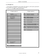
(2) Internal
units
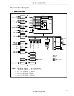
(a) CPU
The CPU uses five-stage pipeline control to enable single-clock execution of address calculations,
arithmetic logic operations, data transfers, and almost all other types of instruction processing.
Other dedicated on-chip hardware, such as a multiplier (16 bits
×
16 bits
→
32 bits) and a barrel shifter
(32 bits) help accelerate complex processing.
(b) Bus control unit (BCU)
The BCU controls the internal bus.
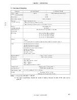
(c) ROM
This consists of a 128 KB mask ROM or flash memory mapped to the address spaces from 0000000H to
001FFFFH.
ROM can be accessed by the CPU in one clock cycle during instruction fetch.
(d) RAM
This consists of a 4 KB RAM mapped to the address spaces from 3FFE000H to 3FFEFFFH.
RAM can be accessed by the CPU in one clock cycle during data access.
(e) Interrupt controller (INTC)
This controller handles hardware interrupt requests (NMI, INTP0 to INTP7) from on-chip peripheral
hardware and external hardware. Eight levels of interrupt priorities can be specified for these interrupt
requests, and multiplexed servicing control can be performed.
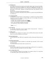
(f) Clock generator (CG)
A main clock oscillator and subclock oscillator are provided and generate the main clock oscillation
frequency (f
X
) and subclock frequency (f
XT
), respectively.
There are two modes: In the clock-through mode, f
X
is used as the main clock frequency (f
XX
) as is. In
the PLL mode, f
X
is used multiplied by 4.
The CPU clock frequency (f
CPU
) can be selected from among f
XX
, f
XX
/2, f
XX
/4, f
XX
/8, f
XX
/16, f
XX
/32, and f
XT
.
(g) Timer/counter
One 16-bit timer/event counter 0 channel, one 16-bit timer/event counter P channel, and two 8-bit
timer/event counter 5 channels are incorporated, enabling measurement of pulse intervals and frequency
as well as programmable pulse output.
Two 8-bit timer/event counter 5 channels can be connected in cascade to configure a 16-bit timer.
Two 8-bit timer H channels enabling programmable pulse output are provided on chip.
(h) Watch timer
This timer counts the reference time (0.5 seconds) for counting the clock from the subclock (32.768 kHz)
or f
BRG
(32.768 kHz) from the clock generator. At the same time, the watch timer can be used as an
interval timer.

