CHAPTER 12 REAL-TIME OUTPUT FUNCTION (RTO)
User’s Manual U16896EJ2V0UD
363
12.7 Security Function
A circuit that sets the pin outputs to high impedance as a security function for when malfunctions of a stepping
motor controlled by RTO occur is provided on chip. It forcibly resets the pins allocated to RTP00 to RTP05 via
external interrupt INTP0 pin edge detection, placing them in the high-impedance state.
The ports (P50 to P55 pins) placed in high impedance by INTP0
Note 1
pin are initialized
Note 2
, so settings for these
ports must be performed again.
Notes 1.
Regardless of the port settings, P50 to P55 pins are all placed in high impedance via the INTP0 pin.
2.
The bits that are initialized are all the bits corresponding to P50 to P55 pins of the following registers.
•
P5 register
•
PM5 register
•
PMC5 register
•
PU5 register
•
PFC5 register
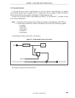
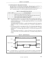
The block diagram of the security function is shown below.
Figure 12-3. Block Diagram of Security Function
Edge detection
INTC
INTP0
RTOST0
RTPOUT00 to RTPOUT05
RTP00 to RTP05
EV
DD
R
6
This function is set with the PLLCTL.RTOST0 bit.

